Difference between revisions of "The Use of Joystick Sensor"
From Microduino Wiki
(Major Edits) |
|||
| Line 40: | Line 40: | ||
===Preparation=== | ===Preparation=== | ||
| − | *Setup | + | *Setup 1: Connect Microduino-Joystick and the Hub 's A0 and A1 analog ports. |
[[file:mCookie-joystick.JPG|600px|center]] | [[file:mCookie-joystick.JPG|600px|center]] | ||
| − | *Setup | + | *Setup 2: Stack the CoreUSB, Hub and Light together and then connect them to the computer with a USB cable. |
[[file:mCookie-joystick.JPG|600px|center]] | [[file:mCookie-joystick.JPG|600px|center]] | ||
| Line 75: | Line 75: | ||
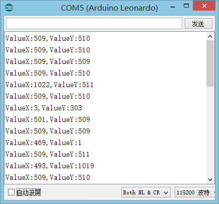
** The top shift value decrease on the Y-axis, close to zero while the downward shift value increases and gets close to 1,023. | ** The top shift value decrease on the Y-axis, close to zero while the downward shift value increases and gets close to 1,023. | ||
===Program Debugging=== | ===Program Debugging=== | ||
| − | * | + | *Use"analogRead(XX);" to read sensor's input analog value and judge the displacement on both the X-axis and Y-axis. |
==Application== | ==Application== | ||
Latest revision as of 06:44, 30 September 2016
ContentsOutlineThe Microduino Joystick sensor is two analog output devices in one. There are resistors on the X-axis and Y-axis that each output an analog value corresponding to the position of the joystick on that axis. This sensor is great for controlling projects, especially ones that move. Specification
DevelopmentEquipment
Preparation
Experiment: Detect Analog Joystick Value
#define Pin_X A1
#define Pin_Y A0

void setup() {
  Serial.begin(9600);    //Serial initializing
  pinMode(Pin_X,INPUT);
  pinMode(Pin_Y,INPUT);
}

void loop() {
  int sensorValueX = analogRead(Pin_X);      //X-axis input
  int sensorValueY = analogRead(Pin_Y);      //Y-axis input
  Serial.print("ValueX:");
  Serial.print(sensorValueX);
  Serial.print(",");
  Serial.print("ValueY:");
  Serial.println(sensorValueY);
  delay(100);
}
Program Debugging
Application
Video |

