Difference between revisions of "Yell at the Alarm"
From Microduino Wiki
(Created page with "{{Language| Voice Control Alarm Clock }} {| style="width: 800px;" |- | ==Objective== You can DIY an alarm clock here. It can wake you up at 7:00 in the morning and the way to ...") |
|||
| Line 17: | Line 17: | ||
|[[Microduino-Sensorhub]]||1||Sensor pin board | |[[Microduino-Sensorhub]]||1||Sensor pin board | ||
|- | |- | ||
| − | |[[Microduino- | + | |[[Microduino-Sound]]||1||Sound detection sensor |
|- | |- | ||
|[[Microduino-BUZZER]]||1||Buzzer sensor | |[[Microduino-BUZZER]]||1||Buzzer sensor | ||
| Line 33: | Line 33: | ||
*Setup 1:Connect the CoreUSB to the computer, open the program examples, select the right board and download the program. | *Setup 1:Connect the CoreUSB to the computer, open the program examples, select the right board and download the program. | ||
[[File:MicroduinoRoarAlarmClock1.jpg|600px|center|thumb]] | [[File:MicroduinoRoarAlarmClock1.jpg|600px|center|thumb]] | ||
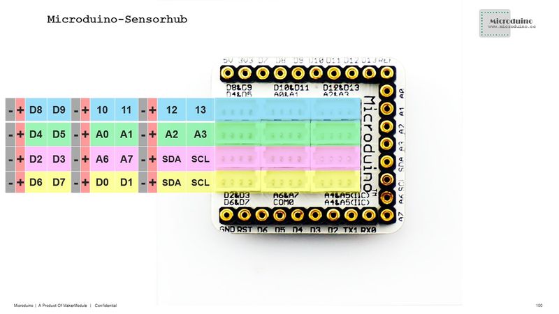
| − | *Setup2:Connect the | + | *Setup2:Connect the Sound to the A2 pin of the Sensorhub, the Buzzer to D6 and the OLED to IIC. |
[[file:Microduino-sensorhub_rule.JPG|thumb|800px|center]] | [[file:Microduino-sensorhub_rule.JPG|thumb|800px|center]] | ||
[[file: MicroduinoRoarAlarmClock2.JPG|thumb|800px|center]] | [[file: MicroduinoRoarAlarmClock2.JPG|thumb|800px|center]] | ||
Latest revision as of 01:59, 25 January 2016
| Language: | English • 中文 |
|---|
ContentsObjectiveYou can DIY an alarm clock here. It can wake you up at 7:00 in the morning and the way to stop it is to shout at it. If you struggle to wake up, it's indeed a great experience to abreact mood by shouting at your noisy alarm clock. PrincipleEquipment
Hardware Buildup
Software DebuggingCode Description
#define buzzer_pin 6

int micPin = A2;
int micValue=0;

U8GLIB_SSD1306_128X64 u8g(U8G_I2C_OPT_NONE);//Define the connection method of the OLED
void initTime() {
  rtc.initClock();
  //set a time to start with.
  //day, weekday, month, century(1=1900, 0=2000), year(0-99)
  rtc.setDate(11, 4, 6, 0, 15);
  //hr, min, sec
  rtc.setTime(13, 5, 0);
}
void updateAlarm() {
  if(timeHH==7&&timeMM<5) {
      if(micValue>500) {
      isRoar=true;
    }
    if(isRoar) {
      noTone(buzzer_pin);
    } else {
      tone(buzzer_pin,500); //Out the frequency in the port.
    }
  } else {
    isRoar=false;
    noTone(buzzer_pin);
  }
}ProgramResultEvery morning at 7:00, the alarm goes on and will last five minutes, during which time you can also interrupt it by shouting at the clock. Video |
