Difference between revisions of "Microduino-Shield Robot"
From Microduino Wiki
| Line 10: | Line 10: | ||
==Feature== | ==Feature== | ||
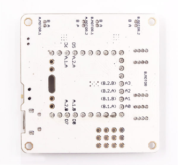
| − | *Two motor | + | *Two motor drive interfaces, capable of driving two stepping motors or four DC motors. |
*Rich sensor interfaces, easy for extension. | *Rich sensor interfaces, easy for extension. | ||
*5V and 3.3V battery management. | *5V and 3.3V battery management. | ||
| Line 22: | Line 22: | ||
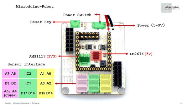
**Please make sure power source within 5V-9V. | **Please make sure power source within 5V-9V. | ||
**Power switch | **Power switch | ||
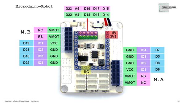
| − | *Motor | + | *Motor drive |
**M.A:D7,D5,D8,D6(suitable for Core and PWM speed adjustment) | **M.A:D7,D5,D8,D6(suitable for Core and PWM speed adjustment) | ||
**M.B:D19,D23,D18,D22(suitable for Core+ and PWM speed adjustment) | **M.B:D19,D23,D18,D22(suitable for Core+ and PWM speed adjustment) | ||
Revision as of 05:44, 29 January 2016
| Language: | English • 中文 |
|---|
|
ContentsFeature
Specification
Document
Development
Program examples: //=========M.A=============//
int mic_left_A = 7;
int mic_right_A = 5;
int mic_head_A = 8;
int mic_back_A = 6;
//=========M.B=============//
/*
int mic_left_B = 22;
int mic_right_B =18;
int mic_head_B = 23;
int mic_back_B = 19;
*/
void setup() {
pinMode(mic_left_A,OUTPUT);
pinMode(mic_right_A,OUTPUT);
pinMode(mic_head_A,OUTPUT);
pinMode(mic_back_A,OUTPUT);
}
void loop() {
head();
delay(1500);
back();
delay(1500);
left();
delay(1500);
right();
delay(1500);
}
void head()
{
digitalWrite(mic_left_A,LOW);
digitalWrite(mic_right_A,HIGH);
digitalWrite(mic_head_A,HIGH);
digitalWrite(mic_back_A,LOW);
}
void left()
{
digitalWrite(mic_left_A,HIGH);
digitalWrite(mic_right_A,LOW);
digitalWrite(mic_head_A,HIGH);
digitalWrite(mic_back_A,LOW );
}
void right()
{
digitalWrite(mic_left_A,LOW);
digitalWrite(mic_right_A,HIGH);
digitalWrite(mic_head_A,LOW);
digitalWrite(mic_back_A,HIGH);
}
void back()
{
digitalWrite(mic_left_A,HIGH);
digitalWrite(mic_right_A,LOW);
digitalWrite(mic_head_A,LOW);
digitalWrite(mic_back_A,HIGH);
}
void stoop()
{
digitalWrite(mic_left_A,LOW);
digitalWrite(mic_right_A,LOW);
digitalWrite(mic_head_A,LOW);
digitalWrite(mic_back_A,LOW);
}
Program example: #include <AccelStepper.h>
const int ENPin_A =8 ; // the number of the LED pin
const int ENPin_B =23 ; // the number of the LED pin
int motorSpeed = 9600; //maximum steps per second (about 3rps / at 16 microsteps)
int motorAccel = 80000; //steps/second/second to accelerate
int motorDirPin_A = 5; //digital pin 5
int motorStepPin_A = 7; //digital pin 7
int motorDirPin_B = 18; //digital pin 5
int motorStepPin_B = 22; //digital pin 7
//set up the accelStepper intance
//the "1" tells it we are using a driver
AccelStepper stepper_A(1, motorStepPin_A, motorDirPin_A);
AccelStepper stepper_B(1, motorStepPin_B, motorDirPin_B);
void setup(){
pinMode(ENPin_A, OUTPUT);
pinMode(ENPin_B, OUTPUT);
stepper_A.setMaxSpeed(motorSpeed);
stepper_A.setSpeed(motorSpeed);
stepper_A.setAcceleration(motorAccel);
stepper_A.moveTo(3200); //move 32000 steps (should be 10 rev)
stepper_B.setMaxSpeed(motorSpeed);
stepper_B.setSpeed(motorSpeed);
stepper_B.setAcceleration(motorAccel);
stepper_B.moveTo(3200); //move 32000 steps (should be 10 rev)
}
void loop(){
digitalWrite(ENPin_A, LOW);
digitalWrite(ENPin_B, LOW);
//if stepper is at desired location
if (stepper_A.distanceToGo() == 0){
//go the other way the same amount of steps
//so if current position is 400 steps out, go position -400
stepper_A.moveTo(-stepper_A.currentPosition());
}
//these must be called as often as possible to ensure smooth operation
//any delay will cause jerky motion
stepper_A.run();
if (stepper_B.distanceToGo() == 0){
//go the other way the same amount of steps
//so if current position is 400 steps out, go position -400
stepper_B.moveTo(-stepper_B.currentPosition());
}
//these must be called as often as possible to ensure smooth operation
//any delay will cause jerky motion
stepper_B.run();
}ApplicationMicroduino-Joypad Self-balance Robot KitBOXZ_mini RobotPurchaseHistoryPictures
Video |
