Difference between revisions of "Buzzer Alarm"
| Line 15: | Line 15: | ||
==Buzzer Description== | ==Buzzer Description== | ||
| − | Buzzer includes active buzzer and passive buzzer. Active buzzer has polarity like LED diodes, whose long pin connects to VCC and the short pin to GND. With that connection, active buzzer can make | + | Buzzer includes active buzzer and passive buzzer. Active buzzer has polarity like LED diodes, whose long pin connects to VCC and the short pin to GND. With that connection, active buzzer can make continuous sounds. The passive buzzer has no polarity. With three pins consisting of two power pins and an audio input pin, the passive buzzer can only make sound in audio output circuit. In this experiment, we will use a passive buzzer. |
==Program== | ==Program== | ||
| Line 51: | Line 51: | ||
*Function description | *Function description | ||
The music coming from Arduino board is controlled by tone(). The change of the function can change the rhythm of the music. The code includes two forms—tone(pin, frequency, duration) and tone(pin, frequency). <br> | The music coming from Arduino board is controlled by tone(). The change of the function can change the rhythm of the music. The code includes two forms—tone(pin, frequency, duration) and tone(pin, frequency). <br> | ||
| − | + | * In the first function, “pin” represents the pin that connects to a loud speaker.<br> | |
| − | + | * If using the second function, then you also need noTone() to control the music. | |
==Debugging== | ==Debugging== | ||
Revision as of 10:35, 6 September 2015
PurposeThis course will show you how to use Microduino buzzer to play simple songs. Equipment
Buzzer DescriptionBuzzer includes active buzzer and passive buzzer. Active buzzer has polarity like LED diodes, whose long pin connects to VCC and the short pin to GND. With that connection, active buzzer can make continuous sounds. The passive buzzer has no polarity. With three pins consisting of two power pins and an audio input pin, the passive buzzer can only make sound in audio output circuit. In this experiment, we will use a passive buzzer. Program
int song[] ={
    262,262,294,262,349,330,
    262,262,294,262,392,349,
    262,262,523,440,349,330,294,
    494,494,440,349,392,349
};

int noteDurations[] = {
  4,4,2,2,2,1,
  4,4,2,2,2,1,
  4,4,2,2,2,2,2,
  4,4,2,2,2,1
};

void setup() {
  for (int thisNote = 0; thisNote<25;thisNote++)
  {
    int noteDuration = 1000/noteDurations[thisNote];
    tone(8, song[thisNote],noteDuration);
    int pauseBetweenNotes = noteDuration *1.30;
    delay(pauseBetweenNotes);
    noTone(8);
  }
}
void loop() {
  setup();
}
The music coming from Arduino board is controlled by tone(). The change of the function can change the rhythm of the music. The code includes two forms—tone(pin, frequency, duration) and tone(pin, frequency).
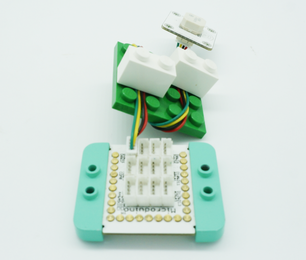
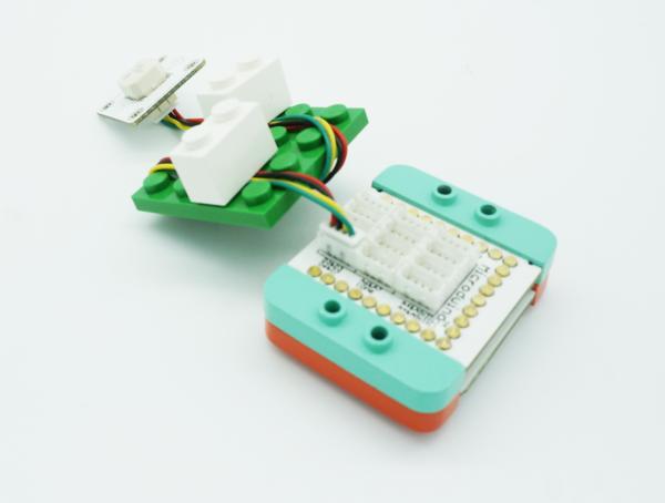
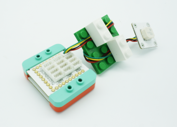
DebuggingStep 1: Insert Microduino buzzer to D8 pin of Microduino-Sensorhub. Step 2: Connect your PC with USB cable, download the code and program it to Microduino-CoreUSB. Step 3: Power on and you’ll hear the music. ResultYou can use the buzzer to play music. |


