Difference between revisions of "Sensor-Crash"

From Microduino Wiki
Jump to: navigation, search
(Application)
Line 1: Line 1:
{{Language|Microduino-Crash Sensor}}
+
{{Language|Sensor-Crash Sensor}}
{| style="width: 800px;"
+
{| style="width: 1000px;"
 
|-
 
|-
 
|
 
|
 
[[File: Microduino Crash-rect.jpg|400px|thumb|right| Microduino-Crash Sensor]]
 
[[File: Microduino Crash-rect.jpg|400px|thumb|right| Microduino-Crash Sensor]]
  
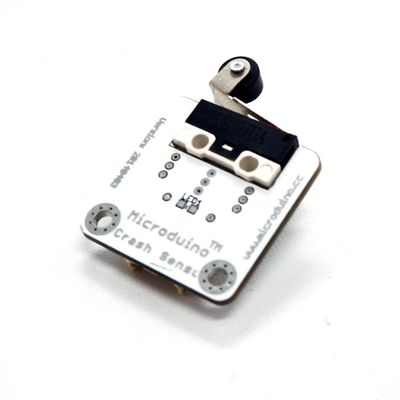
Microduino-Crash Sensor is a sensor which can perceive collision.
+
The product number of Sensor-Crash is : '''MSDS11'''
  
It is used to detect if there is collision or crash. Therefore, it can also be called crash signal sensor. Due to different collision position, it can classified as left-crash sensor or right-crash sensor. Crash switch can turn mechanical quantity to electricity. When this sensor collided with an object, it'll cause circuit switch close. So, the circuit loop will be opened, the LED will be lighten and the voltage between the two sides of the sensor will turn high level to low. Microduino-Crash judges collision by detecting the electrical level between its two side. It can used in limit and anti-collision such as 3D print motor limit switch and robot anti collision. 
+
Sensor-Crash is a crash sensor, which is used to detect whether a crash has happened, and it can be also named crash signal sensor.  
  
 +
Because of the different position of crash, it can be divided into left crash and right crash sensor.


 +
==Introduction of Sensor Pin==
 +
{{Sensor_explain
 +
|nameA=[[Sensor-Crash]]
 +
|modeA=Digital signal input
 +
|modeB=NC
 +
}}
  
 
==Features==
 
==Features==
*Left-crash and right-crash;  
+
*With small size, which is easy to install;
*LED collision indicator;  
+
*It can be used as key switch and limit switch;  
*Small and easy to install.
+
*It feels gentle.
  
 
==Specification==
 
==Specification==
 +
*Sensor voltage
 +
**3.3V~5V working voltage
  
 +
*Size of the sensor
 +
**Size of the board: 23.5mm*13mm
 +
**1.27mm-spacing 4Pin interface connected with sensorhub.
 +
**CAD drawing of the sensor: '''[[File:Sensor_CAD.zip]]'''
  
*Electrical specification
+
*Function description
**Operation voltage: 5V;
+
**The statistic signal of the sensor is HIGH. After being pressed, the signal changes into LOW.
**Input device;
 
*Tech parameters
 
**Pin description: GND, VCC, signal input and NC(Empty);
 
**Digit input.  
 
  
*Size
+
*Connection
**Size of the Switch: 12mm*6mm;
+
**This sensor can be connected to the following interfaces of the core: '''D2~D13''','''A0~A7'''
**Size of the Board: 20mm*20mm;
 
**1.27mm-pitch 4Pin interface connected with Sensorhub.
 
*Connection method
 
**Include left-crash and right-crash. 


[[file:mCookie-sensorhub_rule.JPG|thumb|800px|center]]
 
[[File: Microduino-CRASH Sensor_rule1.jpg|600px|thumb|center]]
 
[[File: Microduino-CRASH Sensor_rule2.jpg|600px|thumb|center]]


==Document==
 
==Document==
*Principle: '''[[File: Microduino_Crash.Zip]]'''
+
*Schematic diagram: '''[[File: Sensor-Crash.Zip.pdf]]'''


==Development==
 
==Development==
===Preparation===
+
===Program Download===
*Make sure you build Microduino development environment. If not, please refer to: [[Microduino Getting started]];
+
*Download and unzip the program '''[[File:Sensor_Crash_Test.zip]]'''
*Choose the core module:
 
**1. Adopt [[Microduino-CoreUSB]] or [[mCookie-CoreUSB]] as the core board;
 
**2.Adopt [[Microduino-Core]] or [[Microduino-Core+]] as the core board and you also need [[Microduino-USBTTL]] to work with the core for program download.


===Program===
 
  
*Open Arduino IDE, select File→Examples→Basics→DigitalReadSerial program example, select the right board, compile and download. 
+
===Programming===
[[file:mCookie-crashCodeExample.JPG|thumb|800px|center]]
+
{{Upload
 +
|nameA=[[Microduino-Core]], [[Microduino-USBTTL]]
 +
|nameB=[[Microduino-USBTTL]]
 +
|boardName=Microduino/mCookie-Core(328p), Atmega328P@16M,5V
 +
|fileName=Sensor_Crash_Test.ino
 +
}}
  
*int pushButton = 6;  Define input pin as D6(Also can be defined by users.)
+
===Hardware Setup===
*pinMode(pushButton, INPUT);    Define pushButton as the input pin.  
+
*Referring to the following diagram, connect the Sensor-Crash to digital port D6 of '''[[Microduino-Sensorhub]]'''.
*int buttonState = digitalRead(pushButton);    Read values of pushButton. 
+
<br>
 +
[[file:Microduino-sensorhub_Crash.JPG|thumb|400px|left]]
 +
<br style="clear: left"/>
  
*Open the serial monitor after download. When there is no collision, the input value is "1" and the input value is "0" under the opposite circumstance. So we can judge if there is collision by input values on the serial monitor.
+
===Result===
 
+
*After download, open the serial monitor.  
===Hardware Buildup===
+
*The static sensor signal is HIGH. After being pressed, it changes into LOW.
*Connect Microduino-Crash and the Sensorhub's digital port(D6) which is also the input pin of "pushButton".  
 
*For reference: [[Microduino-Sensorhub]]
 
[[file:Microduino-sensorhub_6.JPG|thumb|400px|center]]
 
* For reference: [[mCookie-Hub]]
 
[[file:mCookie-sensorhub_6.JPG|thumb|400px|center]]
 
*Connect the core, Sensorhub and LED together to a computer with a USB cable.
 
*Choose the right board and COM port, compile and download. Please refer to: [[AVR Core:Getting started]]
 
[[file:upload.JPG|thumb|800px|center]]
 
*Open the serial communication after download and you'll see button input values.


==Application==
 
==Application==
*Used as a switch;
+
*Key switch
*Used as a crash sensor.
+
*Limit switch
  
===Project===
+
===Projects===
* '''[[Music Box One—Key Version]]'''


==Purchase==


==History==
 
==History==
  
==Pictures==
+
==Gallery==
 
+
{| border="0" cellpadding="10" width="100%"
*Front
+
|-
[[file: Microduino-CRASH Sensor -b.JPG|thumb|600px|center|Microduino-Cube-Station Front]]
+
|width="50%" valign="top" align="left"|
*Back
+
[[file: MicroduinoCrash-F.JPG|thumb|480px|center|mCookie-Crash-Front]]
[[file: Microduino-CRASH Sensor-F.JPG|thumb|600px|center|Microduino-Cube-Station Back]]
+
|width="50%" valign="top" align="left"|
 +
[[file: Microduino-Crash-b.JPG|thumb|480px|center|mCookie-Crash-Back]]
 +
|}
 
|}
 
|}

Revision as of 02:28, 18 September 2016

Language: English  • 中文
Microduino-Crash Sensor

The product number of Sensor-Crash is : MSDS11

Sensor-Crash is a crash sensor, which is used to detect whether a crash has happened, and it can be also named crash signal sensor.

Because of the different position of crash, it can be divided into left crash and right crash sensor.


Introduction of Sensor Pin

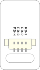
Sensor backpin.png
  • Pins of the sensor:
    • PIN1: GND
    • PIN2: VCC
    • General signal pins:
      • PIN3(IO1): digital/analog signal
      • PIN4(IO2): NC(null)
    • Special signal pins:
      • If it is IIC: IO1/IO2 are respectively SDA/SCL.
      • If it is soft serial port: IO1/IO2 are respectively tx/rx.
  • Special to Sensor-Crash sensor pins
    • PIN1: GND
    • PIN2: VCC
    • PIN3(IO1): Digital signal input
    • PIN4(IO2): NC


Microduino sensor can communicate with core module through the connection with Microduino-Module Sensor Hub.

Features

  • With small size, which is easy to install;
  • It can be used as key switch and limit switch;
  • It feels gentle.

Specification

  • Sensor voltage
    • 3.3V~5V working voltage
  • Size of the sensor
    • Size of the board: 23.5mm*13mm
    • 1.27mm-spacing 4Pin interface connected with sensorhub.
    • CAD drawing of the sensor: File:Sensor CAD.zip
  • Function description
    • The statistic signal of the sensor is HIGH. After being pressed, the signal changes into LOW.
  • Connection
    • This sensor can be connected to the following interfaces of the core: D2~D13,A0~A7

Document

Development

Program Download

Programming

  • Follow the Software Getting Started Guide.
  • Select the Board, Processor and Port.
  • Click [File]->[Open], browse to the project program address, and click "Sensor_Crash_Test.ino" to open the program.
  • After confirming all these items are correct, click "→" to download the program to the development board.

Hardware Setup

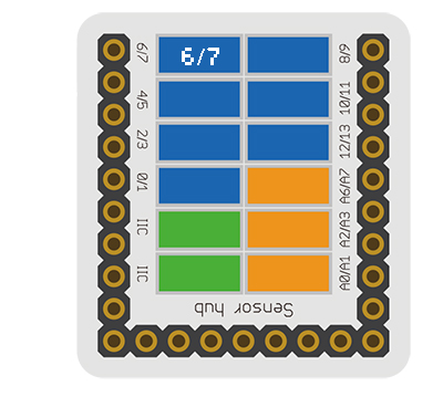
  • Referring to the following diagram, connect the Sensor-Crash to digital port D6 of Microduino-Sensorhub.


Microduino-sensorhub Crash.JPG


Result

  • After download, open the serial monitor.
  • The static sensor signal is HIGH. After being pressed, it changes into LOW.

Application

  • Key switch
  • Limit switch

Projects

History

Gallery

File:MicroduinoCrash-F.JPG
mCookie-Crash-Front
File:Microduino-Crash-b.JPG
mCookie-Crash-Back