Difference between revisions of "Sensor-Gesture"

From Microduino Wiki
Jump to: navigation, search
(Created page with "{{Language|Microduino-Gesture }} {| style="width: 1000px;" | | 400px|thumb|right|mCookie-Hall The product number of mCookie Sensor—Gesture is...")
 
Line 4: Line 4:
 
|
 
|
 
[[File:Microduino-Gesture.jpg|400px|thumb|right|mCookie-Hall]]
 
[[File:Microduino-Gesture.jpg|400px|thumb|right|mCookie-Hall]]
The product number of mCookie Sensor—Gesture is : '''MSDI81'''
+
The product number of mCookie Sensor—Gesture is: '''MSDI81'''
  
 
mCookie Sensor-Gesture is APDS9960.
 
mCookie Sensor-Gesture is APDS9960.
Line 49: Line 49:
  
 
*Schematic diagram: '''[[File: Microduino_Gesture.Zip.pdf]]'''
 
*Schematic diagram: '''[[File: Microduino_Gesture.Zip.pdf]]'''
*HAL49E datasheet:'''[[File: Microduino_Gesture_datasheet.pdf]]'''
+
*HAL49E datasheet: '''[[File: Microduino_Gesture_datasheet.pdf]]'''
 
==Development==
 
==Development==
 
===Program Download===
 
===Program Download===

Revision as of 09:51, 28 September 2016

Language: English  • 中文
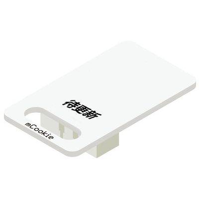
mCookie-Hall

The product number of mCookie Sensor—Gesture is: MSDI81

mCookie Sensor-Gesture is APDS9960.


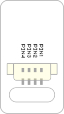
Instruction of Sensor Pin

Sensor backpin.png
  • Pins of the sensor:
    • PIN1: GND
    • PIN2: VCC
    • General signal pins:
      • PIN3(IO1): digital/analog signal
      • PIN4(IO2): NC(null)
    • Special signal pins:
      • If it is IIC: IO1/IO2 are respectively SDA/SCL.
      • If it is soft serial port: IO1/IO2 are respectively tx/rx.
  • Special to Sensor-Gesture sensor pins
    • PIN1: GND
    • PIN2: VCC
    • PIN3(IO1): Analog signal input
    • PIN4(IO2): NC


Microduino sensor can communicate with core module through the connection with Microduino-Module Sensor Hub.


Features

  • With high detection and good stability.
  • A linear hall sensor with a polarity.


Specification

  • Sensor voltage
    • 3.3V~5V working voltage
  • Size of the sensor
    • Sensor of the board: 23.5mm*13mm
    • 1.27mm-spacing 4Pin interface connected with sensorhub
    • CAD drawing of the sensor: File:Sensor CAD.zip
  • Function description
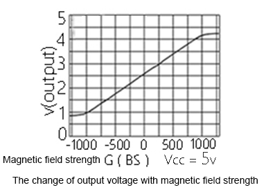
    • This sensor is 10-bit ADC(0~1023), and the static value pin IO1 get is 512.
    • The magnetic strength varies from north to south pole.
      • If approach to the hall circuit with N pole from the back, the output voltage will reduce, and so will the analog value(512~0).
      • If approach to the hall circuit with S pole from the back, the output voltage will increase, and the analog input value will increase(512~1023).
      • If approach from the front, the output state is positive.


  • Microduino-Hall xianxingtu.JPG


  • Connection
    • This sensor can be connected to the following interfaces of the core: A0~A7

Document

Development

Program Download

Programming

  • Follow the Software Getting Started Guide.
  • Select the Board, Processor and Port.
  • Click [File]->[Open], browse to the project program address, and click "Microduino_Gesture_Test.ino" to open the program.
  • After confirming all these items are correct, click "→" to download the program to the development board.

Hardware Setup

  • Referring to the following picture, connect Sensor-Hall to the analog port A0 of Microduino-Sensorhub.


Result

  • After download, open the serial monitor.
    • If approach to the hall circuit with S pole from the back, the output voltage of the two ends of hall sensor is between 2.5V~5V, and the returned analog value is between 512~1023.
    • If approach to the hall circuit with the N pole from the back, the output voltage is between 2.5V~0V, and the returned analog value is between 512~0.
    • If from the front, the output state is positive.

Application

  • It can be used to detect the magnetic field strength.

Projects

Purchase

History

Gallery