Difference between revisions of "Fire Evacuation Drill"
(Created page with "{| style="width: 1000px;" |- | ==Outline== 600px|center Let us make a fire indicating light, which will flash unceasingly to warn people t...") |
|||
| Line 51: | Line 51: | ||
'''"Analog write" program block instruction''' | '''"Analog write" program block instruction''' | ||
<br> | <br> | ||
| − | "Analog write" program block can divide the energy into 256 levels: the lowest is 0, which control the LED to off; the highest is 255, which controls the LED to on, and is the brightest. 0~ | + | "Analog write" program block can divide the energy into 256 levels: the lowest is 0, which control the LED to off; the highest is 255, which controls the LED to on, and is the brightest. Other numbers in 0~255 can make the light light different brightness. |
[[File:mixly-analogoutput-explain.jpg|600px|center]] | [[File:mixly-analogoutput-explain.jpg|600px|center]] | ||
| − | ''' | + | '''Digital output pin of Hub''' |
<br> | <br> | ||
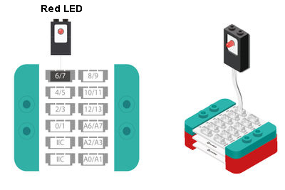
| − | " | + | "Analog output" pin is the interface of the connection between sensors and extension module,and the extension module has 2 analog signal pins: 6/7, 10/11. |
<br> | <br> | ||
[[File:hub-analogoutput-explain.jpg|600px|center]] | [[File:hub-analogoutput-explain.jpg|600px|center]] | ||
<br> | <br> | ||
| − | '''" | + | '''Difference between "digital output" and "analog output" program blocks''' |
| − | *''' | + | *'''Digital output''' |
| − | ** | + | **Just like the switch of the light, it has on and off two states, when the state is off, the light doesn't light, when it is on, the light is the most bright. |
| − | * | + | *Analog output |
| − | ** | + | **Just like the the light dimmer knob of the light, it can make the light change between dark and the most bright, and in the program, it transits between 0~255 levels, 0 representing dark, 255 the most bright. |
[[File:hub-analogoutput-digital.jpg|600px|center]] | [[File:hub-analogoutput-digital.jpg|600px|center]] | ||
| − | ''' | + | '''”Delay” program block''' |
<br> | <br> | ||
| − | + | "Delay" program block is in the "control" tab. | |
[[File:mixly-delay-where.jpg|600px|center]] | [[File:mixly-delay-where.jpg|600px|center]] | ||
| − | + | Introduction of "Delay" program block | |
| − | + | "Delay" program block can make the program stay at the same place for a certain time, and then execute the next program. While the program block is being executed, you can’t do any other things until the end of this time. | |
[[File:mixly-delay-explain.jpg|600px|center]] | [[File:mixly-delay-explain.jpg|600px|center]] | ||
| − | === | + | ===Programming Thought=== |
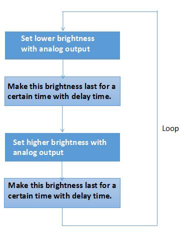
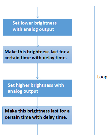
| − | + | If you want to implement the effect of flashing of the LED, you need "analog output" program block to control the brightness of it, and "delay" program block to control the time interval. Through different brightness and time intervals, simulate the light flashing. | |
[[File:mixly-ctrl-ledblink.jpg|600px|center]] | [[File:mixly-ctrl-ledblink.jpg|600px|center]] | ||
| − | === | + | ===Programming=== |
| − | '''1. | + | '''1.LED is on for 1s in weaker brightness. ''' |
<br> | <br> | ||
| − | + | Change the pin of "analog output" into 6, and assign 120 to it; set the delay to 1000ms, namely 1s. | |
[[File:mixly-ctrl-ledblink-code1.jpg|600px|center]] | [[File:mixly-ctrl-ledblink-code1.jpg|600px|center]] | ||
| − | '''2. | + | '''2.LED is on in relatively bright light for 1s''' |
<br> | <br> | ||
| − | + | Change the pin of “analog output” into 6, and assign 240 to it;set the delay time to 1000ms, namely 1s. | |
[[File:mixly-ctrl-ledblink-code2.jpg|600px|center]] | [[File:mixly-ctrl-ledblink-code2.jpg|600px|center]] | ||
| − | 3. | + | 3.Link the two program blocks together, and choose the core and port to download the program. |
<br> | <br> | ||
<br> | <br> | ||
| − | ''' | + | '''Test the result: ''' |
<br> | <br> | ||
| − | + | After upload, if you see the LED flash dark and bright, that is saying our fire alarming light is done! | |
<br> | <br> | ||
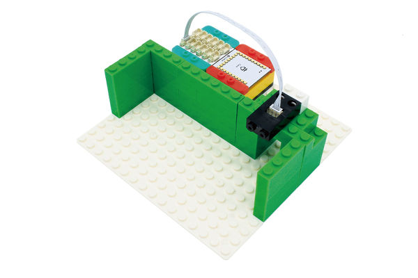
| − | + | Set up an emergency exit with Lego, and install our light on it, then introduce the escape safely knowledge to your friends. | |
[[File:anywhere_light_blink.jpg|600px|center]] | [[File:anywhere_light_blink.jpg|600px|center]] | ||
| − | == | + | ==Can It Be Played in Another Way== |
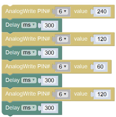
| − | + | Q: Can you set the fire alarming light of three kinds of brightness, and make it flash quicker at the same time? So that it will be easier to attract the intention of people. | |
<br> | <br> | ||
| − | + | A: It is very easy. Just set 3 brightness between 0-255 and make every brightness last shorter time. | |
[[File:mixly-ctrl-ledblink-code3.jpg|600px|center]] | [[File:mixly-ctrl-ledblink-code3.jpg|600px|center]] | ||
| − | == | + | ==FAQ== |
| − | * | + | *Dose the analog output pin of Hub have only 的模拟输出管脚只有6/7,10/11口吗? |
| − | ** | + | **If you adopt Core as the core, you can only choose 6, 7, and the devices outputting analog signal (0-255)must be connected to one of the pins of Hub 6/7, 10/11. Because the analog signal is actually simulated out by the background program with digital signal, you can only use even pins, they are 6 and 10 in Mixly. |
<br> | <br> | ||
| − | ''' | + | '''PWM supporting port of Core''' |
| − | * '''Core''' | + | * '''Core''' PWM supporting, totally 6: |
| − | ** | + | ** On the module labeled D3,D5,D6,D9,D10,D11 |
| − | ** | + | ** For details, please refer to: '''[http://www.arduino.cc/en/Reference/AnalogWrite analogWrite()]''' |
| − | * Core+ | + | * Core+ PWM supporting, totally 8: |
| − | ** | + | ** On the module labeled D7,D8,D9,D10,D12,D13,D22,D23 |
| − | ** | + | ** For details, please refer to: '''[http://www.arduino.cc/en/Reference/AnalogWrite analogWrite()]''' |
|} | |} | ||
Revision as of 04:11, 28 September 2016
|
ContentsOutlineLet us make a fire indicating light, which will flash unceasingly to warn people to leave at once when a fire appear. Suitable kits: mCookie102, mCookie202, mCookie302, IBC
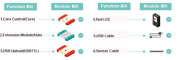
Module BillModule
Other Equipment
Module Setup
ProgrammingLook at the New Program Block"Analog Write" Program Block
"Analog write" program block instruction
Digital output pin of Hub
”Delay” program block
Introduction of "Delay" program block "Delay" program block can make the program stay at the same place for a certain time, and then execute the next program. While the program block is being executed, you can’t do any other things until the end of this time. Programming ThoughtIf you want to implement the effect of flashing of the LED, you need "analog output" program block to control the brightness of it, and "delay" program block to control the time interval. Through different brightness and time intervals, simulate the light flashing. Programming1.LED is on for 1s in weaker brightness.
2.LED is on in relatively bright light for 1s
3.Link the two program blocks together, and choose the core and port to download the program.
Can It Be Played in Another WayQ: Can you set the fire alarming light of three kinds of brightness, and make it flash quicker at the same time? So that it will be easier to attract the intention of people.
FAQ
|
