Difference between revisions of "Revolution Indicator"
(→Start Programming) |
(→Required Program Blocks) |
||
| Line 57: | Line 57: | ||
===Required Program Blocks=== | ===Required Program Blocks=== | ||
| − | *[[“Motor | + | *[[“Motor begin” program block]] |
*[[“Motor choose” program block]] | *[[“Motor choose” program block]] | ||
| − | *[[“ColorLED | + | *[[“ColorLED prepare” program block]] |
| − | |||
*[[“Variable declaration” and “assignment” program blocks]] | *[[“Variable declaration” and “assignment” program blocks]] | ||
| − | *[[ | + | *[[“Rotation potentiometer” program block]] |
*[[“Mapping” program block]] | *[[“Mapping” program block]] | ||
| − | |||
===Start Programming=== | ===Start Programming=== | ||
Revision as of 06:28, 2 June 2017
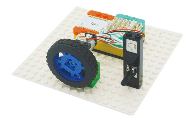
ContentsOverviewToday, we will make a revolution indicator, which can represent the revolution with the color of the indicator light, the brighter the light is, the faster the motor rotates.
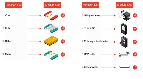
Module ListModule
Other Equipment
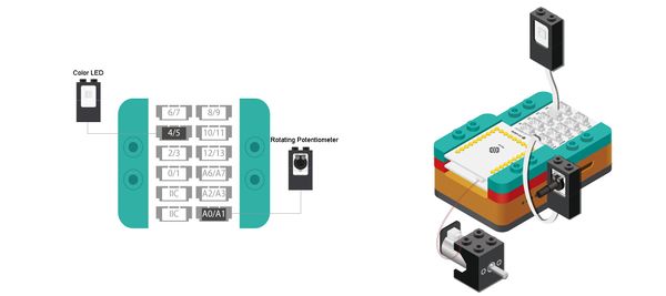
Module SetupSetup
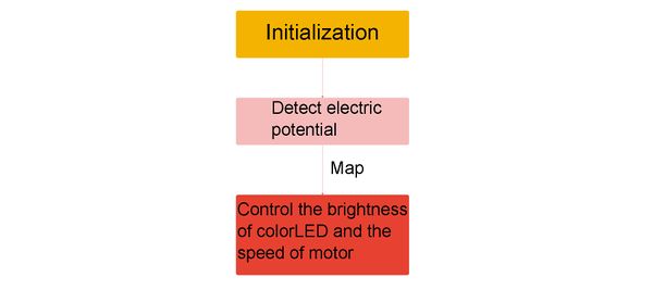
ProgrammingProgramming ThoughtWe can just correspond the set value of the potentiometer to the brightness of the colorLED. Required Program Blocks
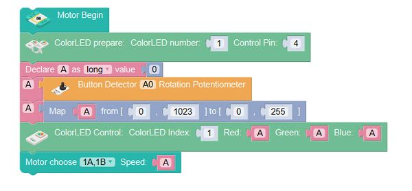
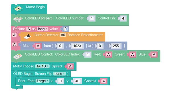
Start ProgrammingMotor begin
ColorLED prepare, connect it to pin 4 of Hub.
Variable A is for storing the speed of the motor.
Save the value of the rotating potentiometer in A.
Map A from 0-1023 to 0-255.
Set the brightness of the color LED to A.
Set the rotation speed of the motor of interface 1A1B to A.
Technical Specification
Related CasesFAQ |
