Difference between revisions of "Various Display of Led Lights"
From Microduino Wiki
(Created page with "{{Language | led花样流水}} {| style="width: 800px;" |- | ==Objective== This tutorial will control 8 LEDs via Processing. ==Equipment== *'''Microduino-Core''' *'''Mi...") |
|||
| Line 15: | Line 15: | ||
**330Ω resistor one | **330Ω resistor one | ||
**Bread one | **Bread one | ||
| − | **Breadboard Jumper | + | **Breadboard Jumper one box |
==Schematic== | ==Schematic== | ||
| Line 25: | Line 25: | ||
https://github.com/Microduino/Microduino_Tutorials/tree/master/Microduino_Processing/sketch_8LEDs | https://github.com/Microduino/Microduino_Tutorials/tree/master/Microduino_Processing/sketch_8LEDs | ||
| − | + | Note: Don't drop the picture in program | |
==Debug== | ==Debug== | ||
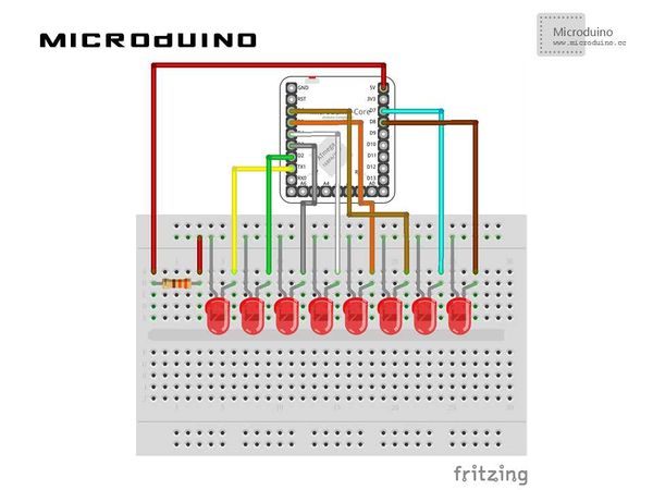
| − | Step | + | Step 1: Set up hardware system, as follows: |
[[File:processingControl8LEDConnectionDiagram.jpg|600px|center|thumb]] | [[File:processingControl8LEDConnectionDiagram.jpg|600px|center|thumb]] | ||
| − | Step | + | Step 2: Explain the code: |
There are two code files in this example: | There are two code files in this example: | ||
| − | LED | + | LED object: |
//Define the variable in object | //Define the variable in object | ||
| Line 68: | Line 68: | ||
| − | + | sketch_8LEDs: Main function | |
//Mouse click function, identify which LED was clicked, then change the button state and LED state after click. | //Mouse click function, identify which LED was clicked, then change the button state and LED state after click. | ||
| Line 88: | Line 88: | ||
==Result== | ==Result== | ||
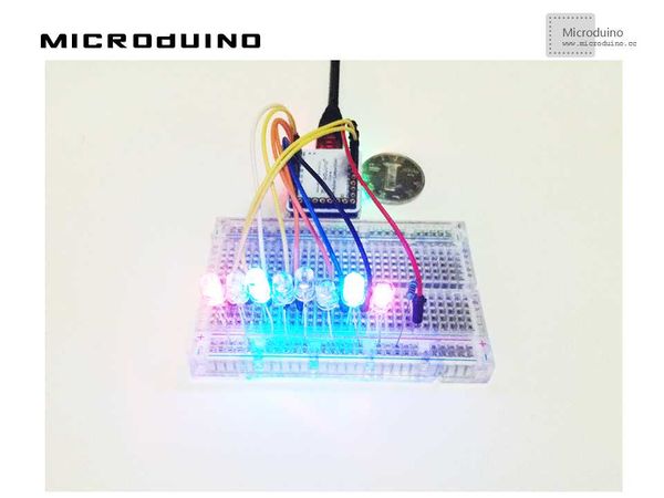
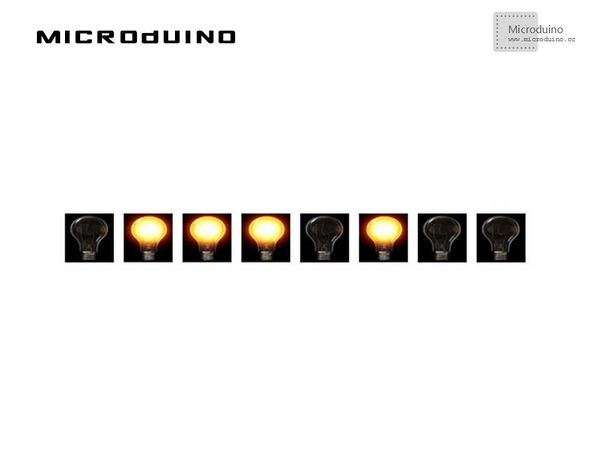
| − | 8 LED will be displayed in screen, you can | + | 8 LED will be displayed in screen, you can control them. |
[[File:processingControl8LEDResult.jpg|600px|center|thumb]] | [[File:processingControl8LEDResult.jpg|600px|center|thumb]] | ||
Latest revision as of 09:03, 13 September 2016
| Language: | English • 中文 |
|---|
ObjectiveThis tutorial will control 8 LEDs via Processing. Equipment
SchematicProgramhttps://github.com/Microduino/Microduino_Tutorials/tree/master/Microduino_Processing/sketch_8LEDs Note: Don't drop the picture in program DebugStep 1: Set up hardware system, as follows:
There are two code files in this example: LED object: //Define the variable in object int xpos;
int ypos;
int w = 50;
int h = 50;
PImage LEDState=loadImage("LEDOFF.png");
int ledPin;
boolean button = false;
 LED(int xpos_, int ypos_, int ledPin_) {
   xpos = xpos_;
   ypos = ypos_;
   ledPin=ledPin_;
 }
//Display function void display() {
if(button) {
LEDState=loadImage("LEDON.png");
} else {
LEDState=loadImage("LEDOFF.png");
}
image(LEDState,xpos,ypos);
}
//Mouse click function, identify which LED was clicked, then change the button state and LED state after click. void mousePressed() {
for (int i = 0; i < leds.length; i ++ ) {
x=leds[i].xpos;
y=leds[i].ypos;
w=leds[i].w;
h=leds[i].h;
if (mouseX > x && mouseX < x+w && mouseY > y && mouseY < y+h) {
leds[i].button = !leds[i].button;
}
}
}
Step 3: Compile the code and download it. Step 4: Click several LED randomly, observe the result. Result8 LED will be displayed in screen, you can control them. Video |


