Open Source Smart Power Plug
ContentsOutline
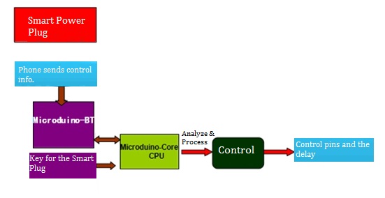
The Smart Power Plug is consisted of the control module and the circuit part. Users can use a phone to connect the Bluetooth module (Microduino-BT ) and send instructions or receive the status of the circuit. The core control module (Microduino-Core) can analyze the data and control the circuit via the relay. Bill of Materials
Principle of the Experiment
The Smart Power Plug can be divided into two parts, voltage conversion and delay control. Let first introduce the voltage conversion. Since the common used voltage at home is 220V and the Microduino-Core works under 5V DC voltage, this part can be treated as a voltage converter, just like a phone power supply plug that can change the voltage. The other part is the relay control. The relay is when the input voltage changes and reaches to the specified requirements, which can make the controlled amount of a predetermined step change in the electrical output circuit. It has an interactive relationship between the controlling system (also known as the input loop) and the controlled system (also known as the output circuit). It is generally used in automatic control circuit, which is actually an "automatic switch" using a small current to control the operation of a large current. Therefore, it plays the automatic regulation, security protection, transformation circuit and so on in the circuit. Since the Microduino-Core control pin's output voltage is very small and it cannot charge appliance directly, It need to control through the relay to indirectly control the household power supply.
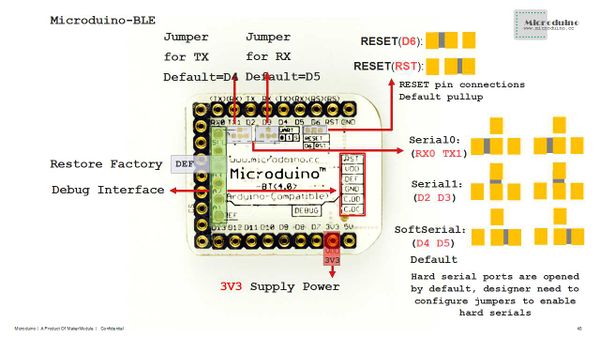
Here we adopt Microduino-BT module since it shields the bottom protocol. Bluetooth protocol will not be classified here and you just need to make sure the default serial port connection method of the Bluetooth is (D2,D3), which can refer to the picture below.
DocumentAddress of the Baidu disk: http://pan.baidu.com/s/1jGjOrR4 The Code: hk0i Debugging
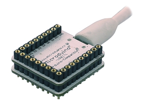
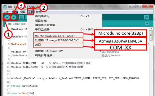
Stack the Microduino-Core and Microduino-USBTTL together, and then upload the pre-written program from Microduino-USBTTL to Microduino-Core with a USB cable. Please be noted to upload the program before stacking all modules. Open Arduino IDE and then click【File】→【Open】. (If you don't have the Arduino IDE on your computer, you can refer to installation method below. ) Find "MicroduinoBluControlOutlet.ino" in the popup dialog, double click it and open. Click the icon "√" on the top left to compile and the Tool, choose the right board card (Microduino-Core Atmega328P@16M,5V) and the port number (COMX). After that, please click "→" and download the program to the development board.
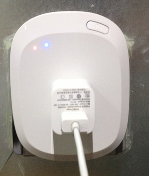
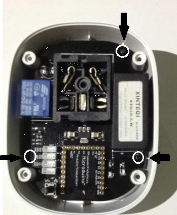
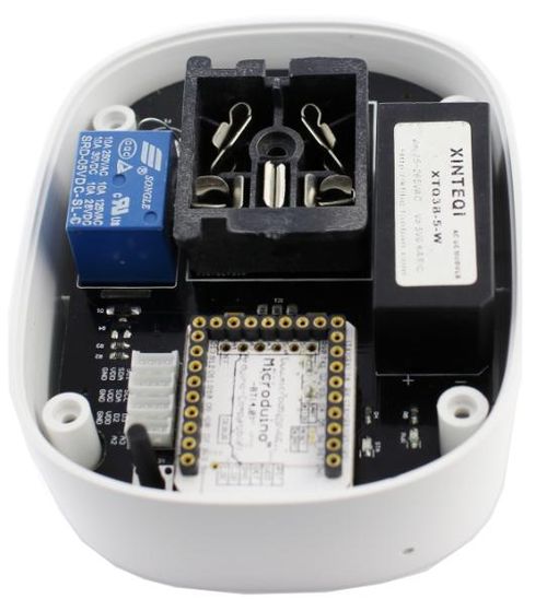
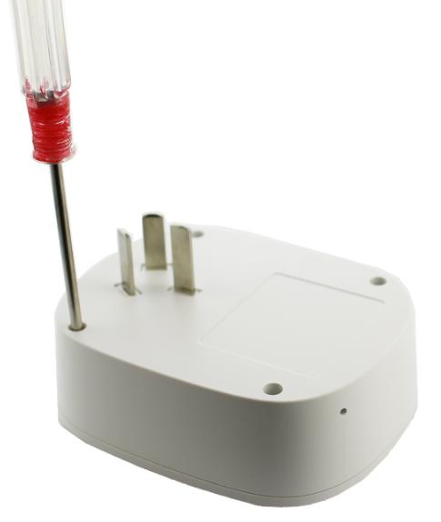
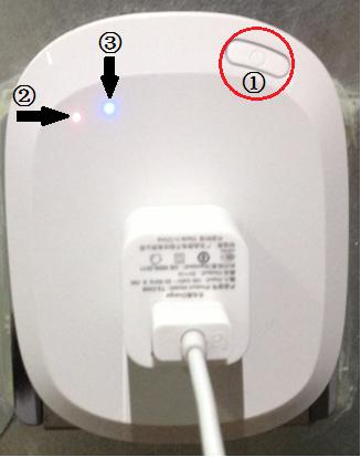
Fixate the circuit board on the bottom case with three 4mm screws. Stack the Microduino-BT and the Microduino-Core, then insert them into the base board of the Smart Plug. Insert the shell into the bottom case and fixate it with 8mm long screws. By here, the buildup of the Smart Plug part is completed. Plug in the Smart Plug into the socket, connect the phone charger and press down the button. You can see the indicator goes on, which means the phone starts charging. As the picture shown below" ①Switch button ②Power-on indicator ③Power-on and off indicator of the Smart Plug
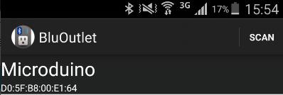
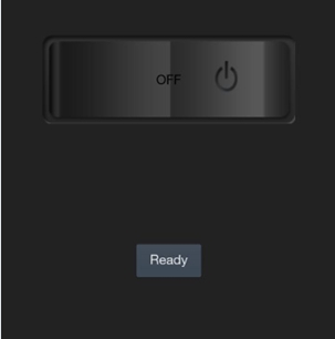
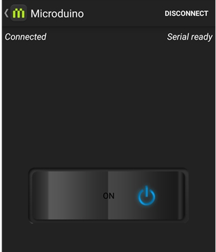
Scan the two-dimension code with your phone, download the Bluetooth APP and open it. Click SCAN, search Bluetooth devices around you, find and click Microduino. Wait for 1-2s until you see "Ready" on the screen, then you can start to operate the Smart Plug. Click the button switch in the middle of the screen and you can control the power-on and off of the Plug, which can also be controlled by the key on the Plug. The phone APP can realize synchronous opening or closing. Notes
Program Description
void loop()
{
    // Read the serial port if there is data received. It needs conversion every time the serial port transmits a character.
    while (my_Serial.available() > 0)
    {

        tmp += char(my_Serial.read());
        delay(2);
    }
    //Judge the status if the content from the serial port is not empty
    if (tmp.length() > 0)
    {
        if(tmp == "on")      //If receives "on"
        {
            Serial.println("power on");  //Serial display: Power on
            digitalWrite(outletPin, HIGH); //Get the switch indicator lightened
            swith = true;
        }
        else if(tmp == "off")  //If receives "off"
        {
            digitalWrite(outletPin, LOW); //Turn off the switch indicator
            Serial.println("power off");//Serial display: Power off
            swith = false;
        }
        tmp = "";
    }

    if(key_get(Button_Pin, 0)) //Used in physical button every time the key is pressed down and get loosened
    {
        delay(300);
        swith = !swith; //Convert the switch status
    }

    if(change != swith) //If the switch status changes
    {
        change = swith; //Record the switch status for the current operation with "Change"
        if(swith)   //If the status is "on"
        {
            digitalWrite(outletPin, HIGH); //Lighten the indicator
            my_Serial.println("ON");     //Notice the BT module to start the Smart Plug
        }
        else
        {
            digitalWrite(outletPin, LOW);  //Close the indicator
            my_Serial.println("OFF");     //Notice the BT module to close the Smart Plug
        }
    }
}
Video |
