Rhythm Lamp
From Microduino Wiki
Revision as of 08:40, 19 June 2015 by 1304410487@qq.com (talk) (Created page with "{{Language| Rhythm Lantern}} {| style="width: 800px;" |- | ==Purpose== To control the color of a lantern by detecting sound via mic sound detection sensor. ==Principle== ==...")
| Language: | English • 中文 |
|---|
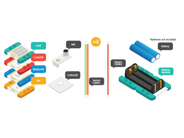
PurposeTo control the color of a lantern by detecting sound via mic sound detection sensor. PrincipleEquipment
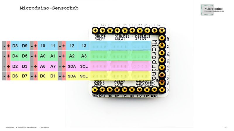
Hardware Buildup
File:Mic colorled.jpg 600px Software Debugging
int v=analogRead(A0);
  switch(zone)
  {
  case 0:
    if(color!=0)
      vol[0]=map(v,0,1023,0,255);
    else
      vol[0]=10;
    break;
  case 1:
    if(color!=1)
      vol[1]=map(v,0,1023,0,255);
    else
      vol[1]=10;
    break;
  case 2:
    if(color!=2)
      vol[2]=map(v,0,1023,0,255);
    else
      vol[2]=10;
    break;
  }

  // Some example procedures showing how to display to the pixels:
colorWipe(strip.Color(vol[0],vol[1], vol[2]), 20);ResultSpeak towards mic and you’ll be suprised about the effect. Video |

