Lesson 2--Microduino "Multiple LEDs"
| Language: | English • 中文 |
|---|
ObjectiveHave learned how to control a LED, now we can go on learn how to control Multiple led flashing turn. Equipment
Experimental schematic
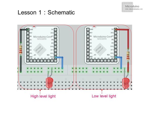
In fact, this is the some principle as Nixie tube control of common cathode and common anode, we will give detailed introduction for how derive Nixie tube. Program
void setup() {
//Define microduino digital I/O port D3~D10 as output
  for(int i=3;i<11;i++)
  pinMode(i, OUTPUT);
}
void loop() {
  for(int i=3;i<11;i++)
  {
  digitalWrite(i, HIGH); // Digital I/O port i(D3~D10) outputs high
  delay(50);            //delay 50ms
  digitalWrite(i, LOW); //// Digital I/O port i(D3~D10) outputs low
  delay(50);           //delay 50ms
  }
}
/*===============================================
ox(High-low:10,9,8,7)(High-low:6,5,4,3)
Example
0x81:10000001
10,9,8,7,6,5,4,3
↓↓↓↓↓↓↓↓
1 0 0 0 0 0 0 1
In common cathode that all led cathode are connected together, 1 on behalf of on, 0 for off,
then use number in the array to control the LED.
=================================================*/
long  data[]=
{
  0x01,0x02,0x04,0x08,0x10,0x20,0x40,0x80,//From left to right light
  0x80,0x40,0x20,0x10,0x08,0x04,0x02,0x01,//From right to left light
  0x81,0x42,0x24,0x18,0x18,0x24,0x42,0x81,//Both sides to the middle and middle to both sides bright light
  0x01,0x03,0x07,0x0f,0x1f,0x3f,0x7f,0xff,//Lit from left to right
  0xff,0x7f,0x3f,0x1f,0x0f,0x07,0x03,0x01,//From right to left extinguished
};

void setup()
{
  for(int x=3;x<11;x++)
  {
    pinMode(x,OUTPUT);//Set the output pin
  }
}


void loop()
{
  for(int x=0;x<40;x++)//Reading different pattern's lights
  {
    leddisplay(data[x]);
    delay(200); //Every state displays 200ms
  }
  leddisplay(0x00);//Cycle is completed, then all extinguished
  delay(200);
}

void leddisplay(int num)    // Mapping the pattern matrix to the port display
{
/*====================================================================
Firstly right shift the hexadecimal number x bits (num >> x),
x represents the microduino I/O port corresponding hexadecimal bit,
0 is the lowest bit, bit 7 is the highest bit.
Then the shifted data with with 0x01 bitwise AND operation and you can get a certain hexadecimal data (0 or 1),
then the value assigned to microduino of I/O port.
 ====================================================================*/
  digitalWrite(3, ((num>>0)&0x01));
  digitalWrite(4, ((num>>1)&0x01));
  digitalWrite(5, ((num>>2)&0x01));
  digitalWrite(6, ((num>>3)&0x01));
  digitalWrite(7, ((num>>4)&0x01));
  digitalWrite(8, ((num>>5)&0x01));
  digitalWrite(9,((num>>6)&0x01));
  digitalWrite(10,((num>>7)&0x01));
}
This experiment similar with the 51 microcontroller running water light writing, assign the hexadecimal array values to the I/O port to light the LED. Such as 0x18 is equivalent to binary 00011000, the corresponding value to "1" on, "0" off. You can write all kinds of tricks randomly. Compared two experiments, the first experiment looks simple, single effect, and the output port must be continuous, and the limitation is very big.The second experiment is optimized, using an array, the hexadecimal number's each value is assigned to the specified I/O port, can realize water light designs.
Result
From left to right in turn cycle lit each led
You can see five pattern effect:From left to right light,From right to left light,Both sides to the middle and middle to both sides bright light,Lit from left to right and From right to left extinguished.
Video |
