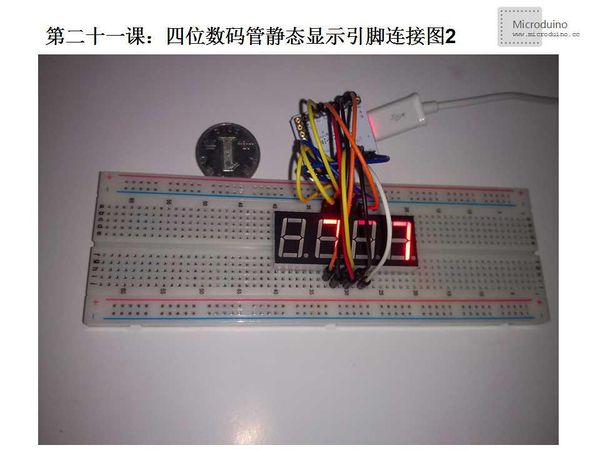
Lesson 21--Microduino Four Digital Tube Static Display
| Language: | English • 中文 |
|---|
ObjectiveThis tutorial will teach you how to use four digital tube display a number. Equipment
Schematic
Program/* Four digital tube controllable display
** Note: In this experiment, use 5416AS chip, it is common cathode. If you are using common anode, need change the HIGH and LOG in some code.
*/
//Set anode interface
//D1 port use to do serial transmission (TX)
int a = 2;//D0,D1 port used for data tranmission, can't be used as digital pin.
int b = 3;
int c = 4;
int d = 5;
int e = 6;
int f = 7;
int g = 8;
int p = 9;//The decimal point
//Set cathode interface (Contro LED 1、2、3、4)
int d1 = 13;//Thousand
int d2 = 12;//Hundred
int d3 = 11;//Ten
int d4 = 10;//One
//Define variable
int del = 5000; //This variable uses to adjust clock
//int changepin = A0;//Input potentiometer data from A0 port
//int val=0;//Save the data from AO port
int val=777;
int val4=0; //The value on Thousand bit, that is the number on DIG1, corresponding pin is d1, Microduino's pin is 13
int val3=0; //The value on Hundred bit, that is the number on DIG2, corresponding pin is d2, Microduino's pin is 12
int val2=0; //The value on Ten bit, that is the number on DIG3, corresponding pin is d3, Microduino's pin is 11
int val1=0; //The value on One bit, that is the number on DIG4, corresponding pin is d4, Microduino's pin is 10
void setup()
{
Serial.begin(9600);//Set baud rate 9600
pinMode(d1, OUTPUT);
pinMode(d2, OUTPUT);
pinMode(d3, OUTPUT);
pinMode(d4, OUTPUT);
pinMode(a, OUTPUT);
pinMode(b, OUTPUT);
pinMode(c, OUTPUT);
pinMode(d, OUTPUT);
pinMode(e, OUTPUT);
pinMode(f, OUTPUT);
pinMode(g, OUTPUT);
pinMode(p, OUTPUT);
}
void loop()
{
//val=analogRead(changepin);//Read the potentiometer value and assigned to val
//Serial.println(val);//Output the val's value from serial
for(int i=0;i<25;i++)//In order to make the changing of digital don't be so sensitive, give a cycle 25 times to meet our requirement
{
//According to the val's digits to display respectively
if(val>=1000)//Four digits number
{
//Note, this uses two algorithm that get one digit from number. Just want to verify these two algorithm both work.
val4=(val/1000)%10; /*For example, 1023 divided by 1000 is equal to 1.023,
get the integer 1, that is the Thousand number. This is the first algorithem. Very simple.*/
val3=( val-((val/1000)%10*1000) )/100%10;
/*For example, 523 divided by 523 is equal to 5.23, integer number is 5, then multiplied by 100 got 500.
Using 523 minus 500 had 23, divided by 10 to get 2.3, got the integer 2, this is a hundred bit number.
This is the second algorithm, a little complicated, but also can be used*/
val2=(val-val/100%10*100)/10%10;
val1= val-val/10%10*10-val/1000%10*1000;
clearLEDs();
pickDigit(1);
pickNumber(val1);
delayMicroseconds(del);
clearLEDs();
pickDigit(2);
pickNumber(val2);
delayMicroseconds(del);
clearLEDs();
pickDigit(3);
pickNumber(val3);
delayMicroseconds(del);
clearLEDs();
pickDigit(4);
pickNumber(val4);
delayMicroseconds(del);
}
else if(val>=100 && val<1000)//Three digits number
{
val3=(val/100)%10;
val2=((val-(((val/100)%10)*100))/10)%10;
val1=val-((val/100)%10)*100-((((val-((val/100)%10)*100)/10)%10)*10);
clearLEDs();
pickDigit(1);
pickNumber(val1);
delayMicroseconds(2*del);
clearLEDs();
pickDigit(2);
pickNumber(val2);
delayMicroseconds(del);
clearLEDs();
pickDigit(3);
pickNumber(val3);
delayMicroseconds(del);
}
else if(val>=10 && val<100)//Two digits number
{
val2=(val/10)%10;
val1=val-(((val/10)%10)*10);
clearLEDs();
pickDigit(1);
pickNumber(val1);
delayMicroseconds(del);
clearLEDs();
pickDigit(2);
pickNumber(val2);
delayMicroseconds(del);
}
else if(val>=0 && val<10)//One digit number
{
val1=val;
clearLEDs();
pickDigit(1);
pickNumber(val1);
delayMicroseconds(del);
}
}
}
void pickDigit(int x) //Define function pickDigit(x) use to enable dx port
{
digitalWrite(d1, HIGH);
digitalWrite(d2, HIGH);
digitalWrite(d3, HIGH);
digitalWrite(d4, HIGH);
if(x==1)
{
digitalWrite(d4, LOW);
}
else if(x==2)
{
digitalWrite(d3, LOW);
}
else if(x==3)
{
digitalWrite(d2, LOW);
}
else if(x==4)
{
digitalWrite(d1, LOW);
}
}
void pickNumber(int x) //Define function pickNumber(x) use to display number x
{
switch(x)
{
default:
zero();
break;
case 1:
one();
break;
case 2:
two();
break;
case 3:
three();
break;
case 4:
four();
break;
case 5:
five();
break;
case 6:
six();
break;
case 7:
seven();
break;
case 8:
eight();
break;
case 9:
nine();
break;
}
}
void clearLEDs() //Clear screen
{
digitalWrite(a, LOW);
digitalWrite(b, LOW);
digitalWrite(c, LOW);
digitalWrite(d, LOW);
digitalWrite(e, LOW);
digitalWrite(f, LOW);
digitalWrite(g, LOW);
digitalWrite(p, LOW);
}
/*
The following code displays number 0 to 9 and decimal point dp, you can also use a two-dimensional array to finish it.
Please refer to blog:http://tahoroom.sinaapp.com/archives/5790.html
*/
void zero() //Define the pin value for number 0
{
digitalWrite(a, HIGH);
digitalWrite(b, HIGH);
digitalWrite(c, HIGH);
digitalWrite(d, HIGH);
digitalWrite(e, HIGH);
digitalWrite(f, HIGH);
digitalWrite(g, LOW);
}
void one() //Define the pin value for number 1
{
digitalWrite(a, LOW);
digitalWrite(b, HIGH);
digitalWrite(c, HIGH);
digitalWrite(d, LOW);
digitalWrite(e, LOW);
digitalWrite(f, LOW);
digitalWrite(g, LOW);
}
void two() //Define the pin value for number 2
{
digitalWrite(a, HIGH);
digitalWrite(b, HIGH);
digitalWrite(c, LOW);
digitalWrite(d, HIGH);
digitalWrite(e, HIGH);
digitalWrite(f, LOW);
digitalWrite(g, HIGH);
}
void three() //Define the pin value for number 3
{
digitalWrite(a, HIGH);
digitalWrite(b, HIGH);
digitalWrite(c, HIGH);
digitalWrite(d, HIGH);
digitalWrite(e, LOW);
digitalWrite(f, LOW);
digitalWrite(g, HIGH);
}
void four() //Define the pin value for number 4
{
digitalWrite(a, LOW);
digitalWrite(b, HIGH);
digitalWrite(c, HIGH);
digitalWrite(d, LOW);
digitalWrite(e, LOW);
digitalWrite(f, HIGH);
digitalWrite(g, HIGH);
}
void five() //Define the pin value for number 5
{
digitalWrite(a, HIGH);
digitalWrite(b, LOW);
digitalWrite(c, HIGH);
digitalWrite(d, HIGH);
digitalWrite(e, LOW);
digitalWrite(f, HIGH);
digitalWrite(g, HIGH);
}
void six() //Define the pin value for number 6
{
digitalWrite(a, HIGH);
digitalWrite(b, LOW);
digitalWrite(c, HIGH);
digitalWrite(d, HIGH);
digitalWrite(e, HIGH);
digitalWrite(f, HIGH);
digitalWrite(g, HIGH);
}
void seven() //Define the pin value for number 7
{
digitalWrite(a, HIGH);
digitalWrite(b, HIGH);
digitalWrite(c, HIGH);
digitalWrite(d, LOW);
digitalWrite(e, LOW);
digitalWrite(f, LOW);
digitalWrite(g, LOW);
}
void eight() //Define the pin value for number 8
{
digitalWrite(a, HIGH);
digitalWrite(b, HIGH);
digitalWrite(c, HIGH);
digitalWrite(d, HIGH);
digitalWrite(e, HIGH);
digitalWrite(f, HIGH);
digitalWrite(g, HIGH);
}
void nine() //Define the pin value for number 9
{
digitalWrite(a, HIGH);
digitalWrite(b, HIGH);
digitalWrite(c, HIGH);
digitalWrite(d, HIGH);
digitalWrite(e, LOW);
digitalWrite(f, HIGH);
digitalWrite(g, HIGH);
}
void dpoint() //Light the decimal point
{
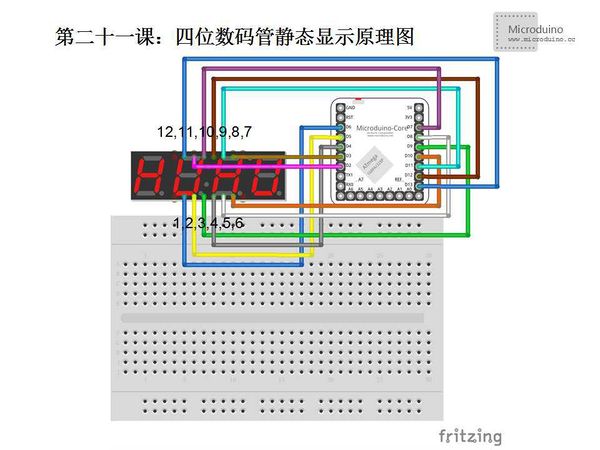
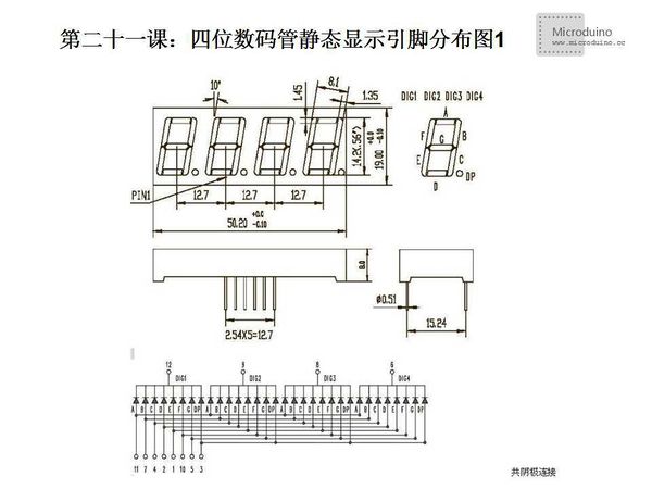
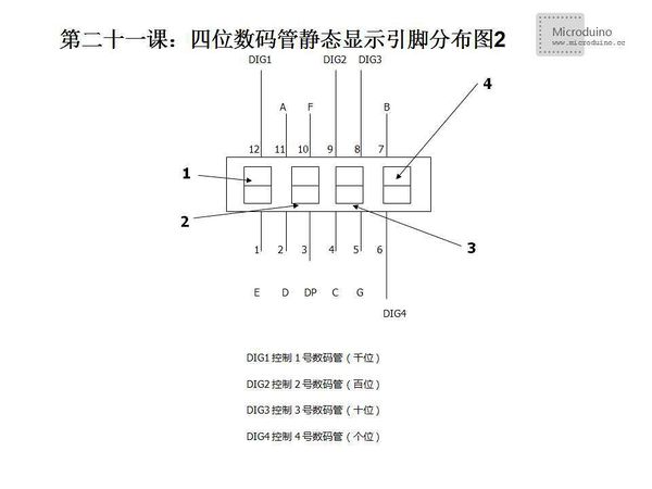
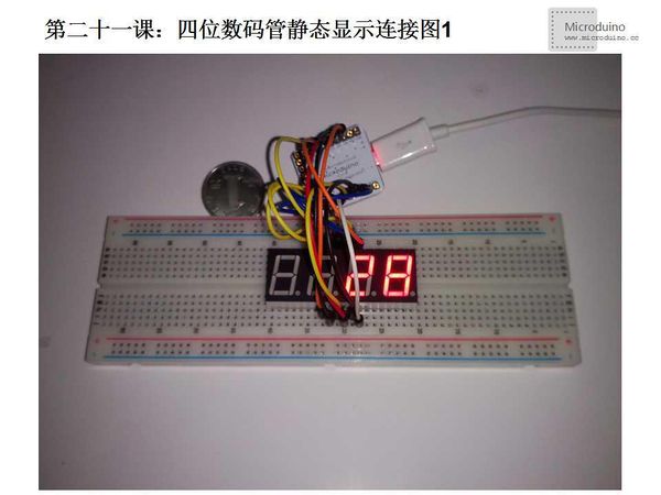
digitalWrite(p, HIGH);
}DebugStep 1:Use 5461AS four digits tube. It is a common cathode tube. (5461BS is common cnode) Different model of digital tube maybe have different pin, so this connection method may not apply to any of the four digital tube, you should know distribution of the digital tube pin before use it. 5461AS four digital tube pin: From the figure, we can see that pin 12, 9, 8, 6 controls the thousand bit, hundred bit, ten bit and one bit (number: 1, 2, 3, 4, later will be used) digital tube on and off. The rest of pins has indicated by number. Although looked from the circuit diagram, pins arranged very irregular, but the distribution is very simple on the physical element. See following diagram. Put the digital tube's positive toward yourself, (decimal point is displayed in the lower right), then the distribution of the pins will be shown in following diagram (lower left corner is 1, reverse direction when the needle is transferred to pin 12. That is the lower left corner is 1, the bottom right hand corner is 6, the upper right corner to 7, the upper left corner of 12). If you don't want to remember it, you can use marker pen write the pin number on the side of the digital tube, convenient for later use. Step 2:Copy the code it IDE and compile it Here need to talk about what are the common cathode and common anode. Common cathode means that all the control pins connect to the anode respectively, the HIGH on, LOW off. Common anode, by contrast, the output level is HIGH for off, and LOW is for on. but bright. In this experiment, we use 5461AS the four digital tube, it is a common cathode digital tube (5461BS is a commom anode digital tube). So all control digital pins is HIGH will light LED. Step 3:Set up circuit, as follows: Step 4:Run program Step 5:Observe digital tube ResultFout digits tube will display four digits number. Video |
