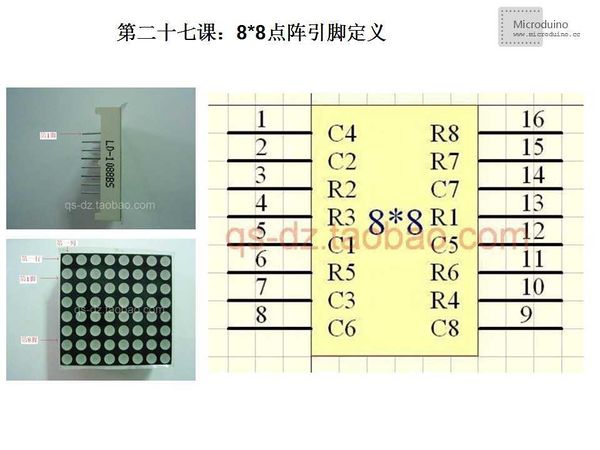
Lesson 27--Microduino 8*8 Lattice Static Display
| Language: | English • 中文 |
|---|
ObjectiveThe tutorial will teach you use two 74HC595 to control 8** lattice and display a static smiling faces. Equipment
Schematice
Program //Pin connects to 74HC595的ST_CP
int latchPin = 8;
//Pin connects to 74HC595的SH_CP
int clockPin = 12;
////Pin connects to 74HC595的DS
int dataPin = 11;
void setup() {
//Set barud roate 9600
Serial.begin(9600);
//Set the latchpin as output
pinMode(latchPin, OUTPUT);
}
void loop() {
//Smile for 8x8 Matrix LED
digitalWrite(latchPin, 0);
shiftOut(dataPin, clockPin, B01111111); //col
shiftOut(dataPin, clockPin, B00111100); //row
digitalWrite(latchPin, 1);
digitalWrite(latchPin, 0);
shiftOut(dataPin, clockPin, B10111111); //col
shiftOut(dataPin, clockPin, B01000010); //row
digitalWrite(latchPin, 1);
digitalWrite(latchPin, 0);
shiftOut(dataPin, clockPin, B11011111); //col
shiftOut(dataPin, clockPin, B10100101); //row
digitalWrite(latchPin, 1);
digitalWrite(latchPin, 0);
shiftOut(dataPin, clockPin, B11101111); //col
shiftOut(dataPin, clockPin, B10000001); //row
digitalWrite(latchPin, 1);
digitalWrite(latchPin, 0);
shiftOut(dataPin, clockPin, B11110111); //col
shiftOut(dataPin, clockPin, B10100101); //row
digitalWrite(latchPin, 1);
digitalWrite(latchPin, 0);
shiftOut(dataPin, clockPin, B11111011); //col
shiftOut(dataPin, clockPin, B10011001); //row
digitalWrite(latchPin, 1);
digitalWrite(latchPin, 0);
shiftOut(dataPin, clockPin, B11111101); //col)
shiftOut(dataPin, clockPin, B01000010); //row
digitalWrite(latchPin, 1);
digitalWrite(latchPin, 0);
shiftOut(dataPin, clockPin, B11111110); //col
shiftOut(dataPin, clockPin, B00111100); //row
digitalWrite(latchPin, 1);
}
void shiftOut(int myDataPin, int myClockPin, byte myDataOut) {
//initialization
int i=0;
int pinState;
pinMode(myClockPin, OUTPUT);
pinMode(myDataPin, OUTPUT);
//clear everything out just in case to
//prepare shift register for bit shifting
digitalWrite(myDataPin, 0);
digitalWrite(myClockPin, 0);
//for each bit in the byte myDataOut�
//NOTICE THAT WE ARE COUNTING DOWN in our for loop
//This means that %00000001 or "1" will go through such
//that it will be pin Q0 that lights.
for (i=7; i>=0; i--) {
digitalWrite(myClockPin, 0);
//if the value passed to myDataOut and a bitmask result
// true then... so if we are at i=6 and our value is
// %11010100 it would the code compares it to %01000000
// and proceeds to set pinState to 1.
if ( myDataOut & (1<<i) ) {
pinState= 1;
}
else {
pinState= 0;
}
//Sets the pin to HIGH or LOW depending on pinState
digitalWrite(myDataPin, pinState);
//register shifts bits on upstroke of clock pin
digitalWrite(myClockPin, 1);
//zero the data pin after shift to prevent bleed through
digitalWrite(myDataPin, 0);
}
//stop shifting
digitalWrite(myClockPin, 0);
}DebugStep 1:Copy the code to IDE and compile it Step 2:Set up circuit, as follows: In order to protect the circuit, plus a 220Ω registor on the every connection line (total 8 lines) between one 74HC595 chip and 8*8 latteice LED. In our example, we don't use the registor, so the LED's brightnees is strong. If the lattice's quality is bad and easily broken. Step 3:Run program Result8*8 lattice LED will diaplya a smiling face. Video |


