Lesson 28--Microduino & Raindrop Sensor
Microduino & Raindrop Sensor
ContentsPurposeLet’s talk about raindrop sensor in this course and make some interesting applications with Microduino and the sensor. EquipmentMicroduino-Core is the 8-bit single-chip development core board with Atmel ATmega328P as the core, which is an open and Arduino Uno compatible controller. Microduino-USBTTL is the program download module, capable of connecting with Microduino-Core or Microduino-Core+ and making the modules communicate with the computer. It uses MicUSB as the download interface, which is also the smallest part of Microduino. Microduino is just as small as a quarter. Besides, the download cable is just like the USB cable of most smart phones, easy to use.
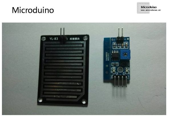
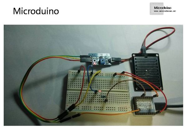
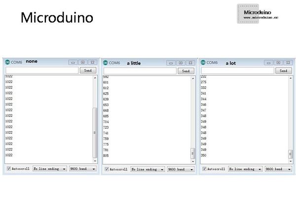
Raindrop sensorWhen raindrop falls on the sensor, the digital quantity output port of the sensor can output low electrical level. The analog quantity output port can change output voltage according to the quantity of the rain. The more the raindrop gets, the lower the voltage is. When the sensor detects no water, the port will output high electrical level and the output voltage is Vcc(Supply voltage). There are two LED lights on PCB board, one is for power indicator and the other is for raindrop indicator. When the raindrop indicator goes on, it means the digital output of the module is low and Microduino can detect the electrical level and then handle it. Besides, you can also adjust sensitivity of the potentiometer. With different sensitivity, one or two raindrop can have the same effect. SchematicMicroduino's A0 port is connected with the analog output of the raindrop module, whose D2 port is connected to LED via a 510 Ω resistor. (LED's cathode is connected to the ground.) Programvoid setup()
{
pinMode(2,OUTPUT);
Serial.begin(9600);
}
void loop()
{
int value=analogRead(A0);
Serial.println(value);
if(value<800)//You can change this value to fit for your app
digitalWrite(2,HIGH);//Open the led
else
digitalWrite(2,LOW);//close
delay(1000);
}Debugging
ResultWe can utilize the electrical level change or analog quantity output of the raindrop sensor based on different requirements. Eg. we can control the change of Microduino's PWM duty cycle as well as motor speed according to the change of the raindrop sensor's analog port output voltage. Video |


