Lesson 46--Microduino Piano Touch
ContentsObjectiveIn this tutorial, we'll first explain how to measure capacitance with Microduino and then simulate finger switch and electronic piano just like how we do with Makey, Makey. Equipment
How to measure capacitanceHere is the basic idea of the experiment: First, set one digital port to low level and open Microduino interior pull-up resistor and begin to count time needed by reaching high level. The specific time is related to ground capacitance value of the port. The bigger the capacitance is, the longer the time gets. In terms of hardware, you only need to connect a wire to one port and then touh the other side with your finger, which will cause capacitance change and Microduino can measure the change therefore. If wanting to add flexibility, you can put a tinfoil on the other side of the wire and cover a piece of insulation paper in order to avoid strong static electricity shock on the chip from your hand.
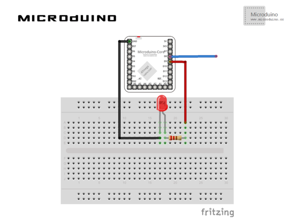
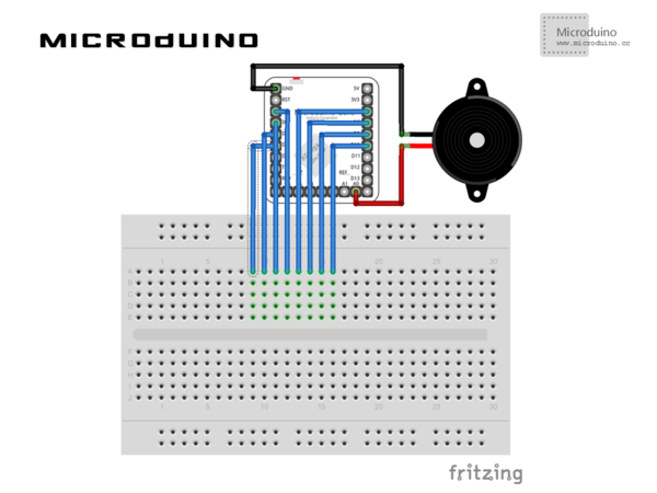
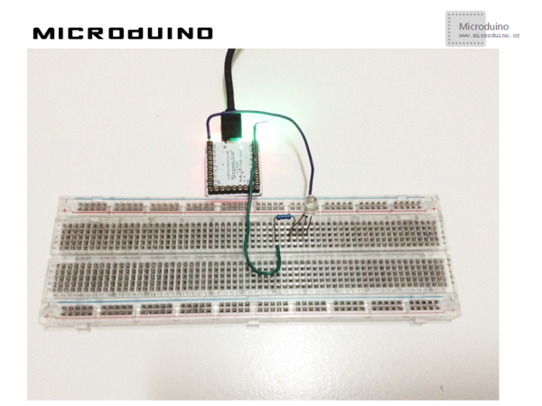
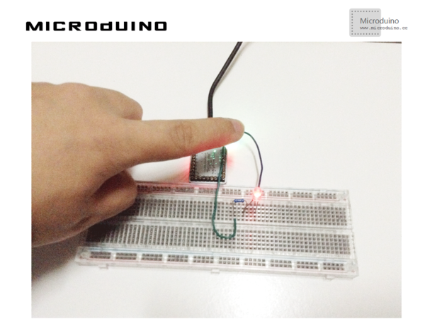
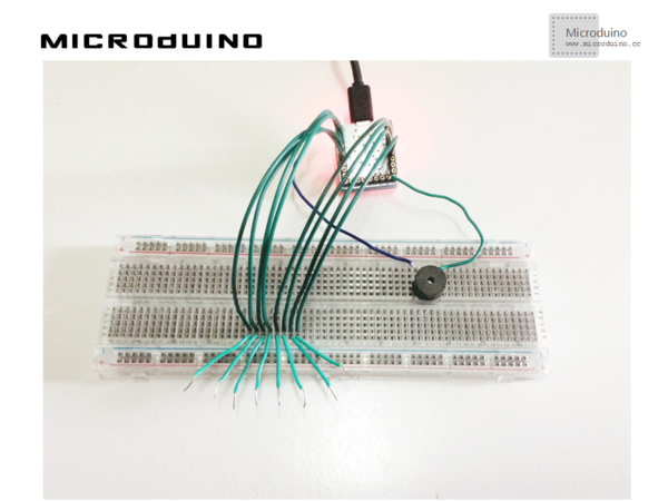
SchematicProgramTouch switch: capacityMeature Touch piano: chumomusic Debugging=1. Build circuit environment according to schematic, just like this: 2. Download code and run. When fingers touch the contactor, the LED goes on. 3. Build circuit environment according to schematic, as follows: 4. Download code and run. When fingers touches contactors from left to right, the pitch rises in order. ResultIn this experiment, you can achieve finger touch LED and electronic piano. Below is the video link showing TWO TIGERS. Video |
