Difference between revisions of "Microduino-Joypad Getting start"
From Microduino Wiki
(Blanked the page) |
|||
| Line 1: | Line 1: | ||
| + | {| style="width: 800px;" | ||
| + | |- | ||
| + | | | ||
| + | *Microduino modules needed | ||
| + | {|class="wikitable" | ||
| + | |- | ||
| + | |Module||Number||Function | ||
| + | |- | ||
| + | |[[Microduino-Joypad]] ||1||Remote controller | ||
| + | |- | ||
| + | |[[Microduino-Core ]]||1||Core board | ||
| + | |- | ||
| + | |[[Microduino-USBTTL]]||1||Program download | ||
| + | |} | ||
| + | *Other Equipment | ||
| + | {|class="wikitable" | ||
| + | |- | ||
| + | |Module||Number||Function | ||
| + | |- | ||
| + | | USB cable|| 1||Data transmission | ||
| + | |- | ||
| + | | Battery box || 1||Battery load | ||
| + | |- | ||
| + | |7th battery ||3 ||Power supply | ||
| + | |} | ||
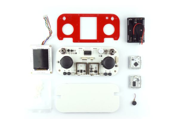
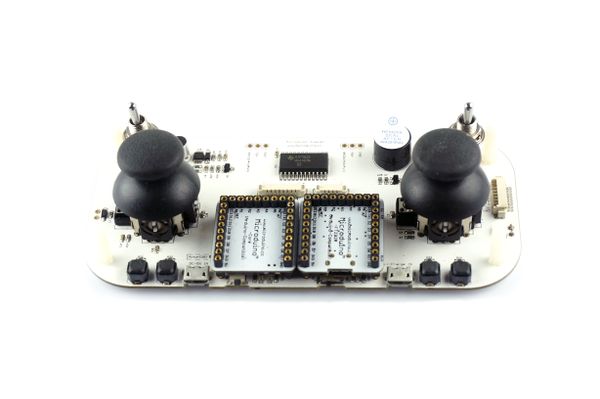
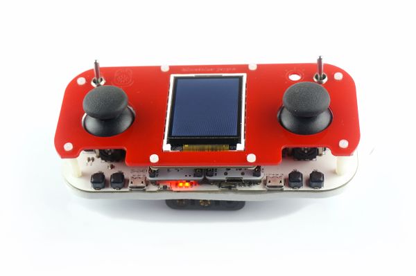
| + | [[File:Microduino_Joypad_TFT-all.jpg||600px|center|thumb]] | ||
| + | |||
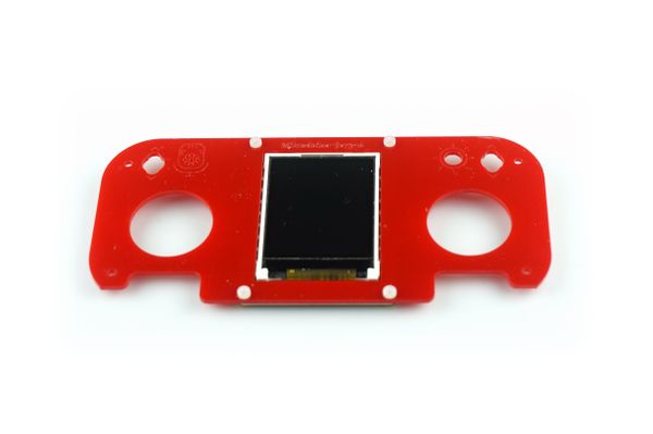
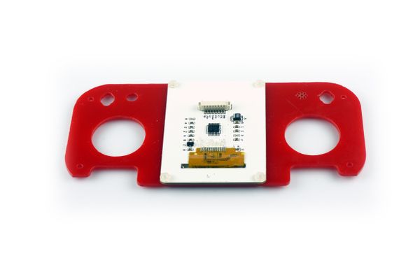
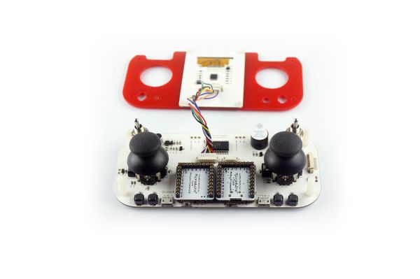
| + | *Step 1: Install Microduino-TFT on the panel of Microduino-Joypad; | ||
| + | [[File:Microduino_Joypad_TFT-1.jpg||600px|center|thumb]] | ||
| + | [[File:Microduino_Joypad_TFT-2.jpg||600px|center|thumb]] | ||
| + | |||
| + | *Step 2: Fixate plastic fasteners on Microduino-Joypad; | ||
| + | [[File:Microduino_Joypad_nilong-1.jpg||600px|center|thumb]] | ||
| + | |||
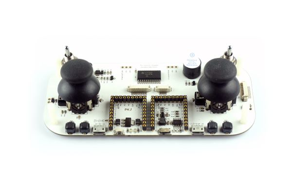
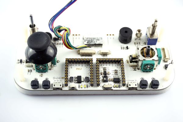
| + | *Step 3: Stack Microduino-USBTTL, Microduino-Core on the base board of Microduino-Joypad. | ||
| + | [[File:Microduino_Joypad_Module-1.jpg||600px|center|thumb]] | ||
| + | |||
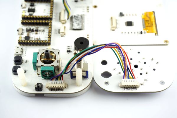
| + | *Step 4: Connect Microduino-TFT and Microduino-Joypad through adapter cable; | ||
| + | [[File:Microduino_Joypad_1.jpg||600px|center|thumb]] | ||
| + | |||
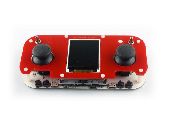
| + | *Step 5: Fixate the panel and the base board with plastic fasteners; | ||
| + | [[File:Microduino_Joypad_face_bord-1.jpg||600px|center|thumb]] | ||
| + | |||
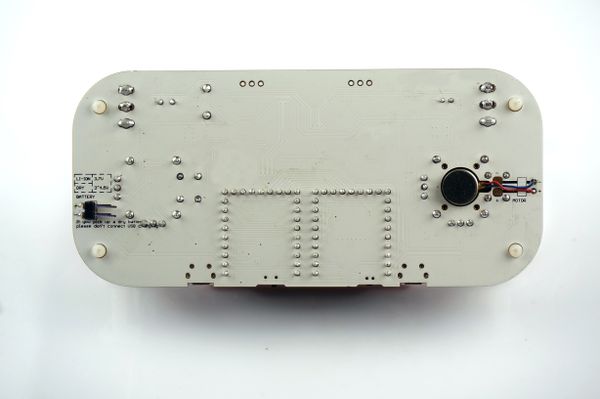
| + | *Step 6: If there is vibration, please install vibration motor; | ||
| + | [[File:Microduino_Joypad_shock-1.jpg||600px|center|thumb]] | ||
| + | |||
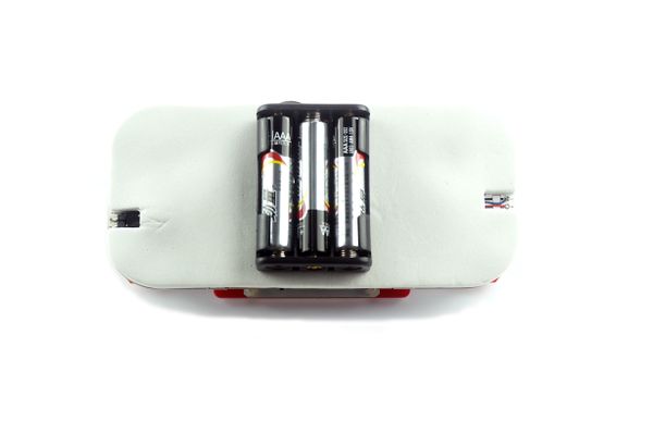
| + | *Step 7: Connect the battery box on the base board and make sure the electrodes are connected correctly, then paste the board at the bottom of Microduino-Joypad; | ||
| + | [[File:Microduino_Joypad_power_1.jpg||600px|center|thumb]] | ||
| + | |||
| + | |||
| + | *Step 8: You can power on and see if the power supply works fine or not. | ||
| + | [[File:Microduino_Joypad_switch-2.jpg||600px|center|thumb]] | ||
| + | |||
| + | *If you want to install Microduino-Joypad-Game board, you need to take off the right joystick. | ||
| + | |||
| + | [[File:Microduino_Joypad_keyboard_1.jpg||600px|center|thumb]] | ||
| + | |||
| + | *Connect the interface of the key and the base board on the panel by a connector. | ||
| + | [[File:Microduino_Joypad_keyboard_2.jpg||600px|center|thumb]] | ||
| + | *Fixate the panel with fasteners. | ||
| + | [[File:Microduino_Joypad_keyboard_3.jpg||600px|center|thumb]] | ||
| + | |||
| + | ==Test== | ||
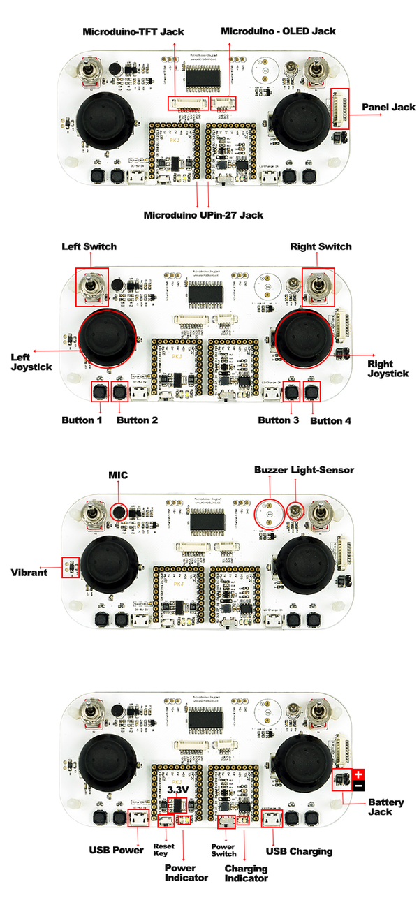
| + | *Two parallel UPIN27 base boards; | ||
| + | *Two switches; | ||
| + | *Four buttons; | ||
| + | *MIC sound detection input; | ||
| + | *Photosensitive detection input; | ||
| + | *Buzzer output, connected to D6 pin of Microduino; | ||
| + | *Vibration motor output, connected to D8 pin of Microduino; | ||
| + | *On-board Micro USB power supply, charging management and 3.3V stability. | ||
| + | *2.54-inch pitch for power supply interface. | ||
| + | |||
| + | [[File:Microduino-Joypad-Expansion.png|600px|thumb|center|Microduino-Joypad-Expansion]] | ||
| + | |||
| + | *Libraries needed: | ||
| + | **https://github.com/wasdpkj/libraries | ||
| + | You will need _01_Microduino_TFT and _08_Microduino_Shield_Joypad library. | ||
| + | *Debugging: | ||
| + | **Hardware needed: Microduino-USBTTL, Microduino-Core and the equipped Microduino-Joypad | ||
| + | **Software needed: libraries and Arduino IDE; | ||
| + | **Decompress and download the library file and copy it to libraries of Arduino IDE; Decompress and download library file and then copy it to libraries of Arduino IDE; | ||
| + | **Re-open “Arduino-IDE” and you can select examples in “_08_Microduino_Shield_Joypad\examples”. After successful compiling, choose the board Microduino Core (Atmega328P@16M,5V) and then download; | ||
| + | ===Program Description=== | ||
| + | *Read: | ||
| + | **Read the value of A and B about illumination, MIC, extension interface. The return value should be within int(0~1023); <source lang="cpp"> | ||
| + | //Illumination---------------------- | ||
| + | Joypad.readLightSensor(); | ||
| + | //MIC-------------------- | ||
| + | Joypad.readMicrophone(); | ||
| + | //INTA---------------------- | ||
| + | Joypad.readIntA(); | ||
| + | //INTB---------------------- | ||
| + | Joypad.readIntB(); | ||
| + | </source> | ||
| + | |||
| + | **Read values of the left and the right analog joysticks. The return value is: int(-512~512); | ||
| + | <source lang="cpp"> | ||
| + | |||
| + | //Left analog joystick---------------- | ||
| + | Joypad.readJoystickX(); | ||
| + | Joypad.readJoystickY(); | ||
| + | |||
| + | //Right analog joystick---------------- | ||
| + | Joypad.readJoystick1X(); | ||
| + | Joypad.readJoystick1Y(); | ||
| + | </source> | ||
| + | |||
| + | **Read the left and the right analog joystick values; The return value of the left-and-right analog joystick, switches, four-group-of-button are: Boolean(HIGH、LOW); | ||
| + | |||
| + | <source lang="cpp"> | ||
| + | |||
| + | Joypad.readButton(byte ch); | ||
| + | //Left analog joystick---------------- | ||
| + | JOYSTICK_UP; | ||
| + | JOYSTICK_DOWN; | ||
| + | JOYSTICK_LEFT; | ||
| + | JOYSTICK_RIGHT; | ||
| + | |||
| + | //Left analog joystick press------------ | ||
| + | CH_JOYSTICK_SW | ||
| + | |||
| + | //Right analog joystick---------------- | ||
| + | JOYSTICK1_UP; | ||
| + | JOYSTICK1_DOWN; | ||
| + | JOYSTICK1_LEFT; | ||
| + | JOYSTICK1_RIGHT; | ||
| + | |||
| + | //Right analog joystick press ------------ | ||
| + | CH_JOYSTICK1_SW | ||
| + | |||
| + | //Switch ------------------ | ||
| + | CH_SWITCH_L; | ||
| + | CH_SWITCH_R; | ||
| + | |||
| + | //Four groups of buttons------------------ | ||
| + | CH_SWITCH_1; | ||
| + | CH_SWITCH_2; | ||
| + | CH_SWITCH_3; | ||
| + | CH_SWITCH_4; | ||
| + | </source> | ||
| + | |||
| + | *Write: | ||
| + | **Control buzzer and vibration; | ||
| + | <source lang="cpp"> | ||
| + | //========================== | ||
| + | //Buzzer--------------------- | ||
| + | Joypad.tone(unsigned int freq); | ||
| + | Joypad.tone(unsigned int freq, unsigned long duration); | ||
| + | Joypad.noTone(); | ||
| + | |||
| + | //Vibration------------------------ | ||
| + | Joypad.motor(unsigned int motor_vol); | ||
| + | “unsigned int motor_vol”:Vibration intensity | ||
| + | </source> | ||
| + | |||
| + | ==Start Application== | ||
| + | [[Microduino-Joypad Application Tutorial]] | ||
| + | |} | ||
Revision as of 02:58, 25 November 2014
Test
You will need _01_Microduino_TFT and _08_Microduino_Shield_Joypad library.
Program Description
	//Left analog joystick----------------
	Joypad.readJoystickX();
	Joypad.readJoystickY();

	//Right analog joystick----------------
	Joypad.readJoystick1X();
	Joypad.readJoystick1Y();
	Joypad.readButton(byte ch);
	//Left analog joystick----------------
		JOYSTICK_UP;
		JOYSTICK_DOWN;
		JOYSTICK_LEFT;
		JOYSTICK_RIGHT;

	//Left analog joystick press------------
		CH_JOYSTICK_SW

	//Right analog joystick----------------
		JOYSTICK1_UP;
		JOYSTICK1_DOWN;
		JOYSTICK1_LEFT;
		JOYSTICK1_RIGHT;

	//Right analog joystick press ------------
		CH_JOYSTICK1_SW

	//Switch ------------------
		CH_SWITCH_L;
		CH_SWITCH_R;

	//Four groups of buttons------------------
		CH_SWITCH_1;
		CH_SWITCH_2;
		CH_SWITCH_3;
		CH_SWITCH_4;
//==========================
	//Buzzer---------------------
  Joypad.tone(unsigned int freq);
  Joypad.tone(unsigned int freq, unsigned long duration);
  Joypad.noTone();

//Vibration------------------------
Joypad.motor(unsigned int motor_vol);
“unsigned int motor_vol”:Vibration intensity
Start Application |
