Sensor-IO Split

From Microduino Wiki
Revision as of 07:00, 11 November 2016 by Fengfeng (talk)
Jump to: navigation, search
Language: English  • 中文
Sensor-IO split


The product number of Sensor-IO Split is: MSDE21

Sensor-IO-split can split a 4PIN interface into 2.

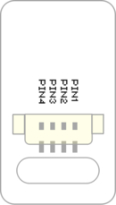
Introduction of Pins

Sensor backpin.png
  • Pins of the sensor:
    • PIN1: GND
    • PIN2: VCC
    • General signal pins:
      • PIN3(IO1): digital/analog signal
      • PIN4(IO2): NC(null)
    • Special signal pins:
      • If it is IIC: IO1/IO2 are respectively SDA/SCL.
      • If it is soft serial port: IO1/IO2 are respectively tx/rx.
  • Special to Sensor-IO Split sensor pins
    • PIN1: GND
    • PIN2: VCC
    • PIN3(IO1): IO1
    • PIN4(IO2): IO2


Microduino sensor can communicate with core module through the connection with Microduino-Module Sensor Hub.


  • All interfaces of Sensor-IO Split are 1.27mm-spacing 4Pin.
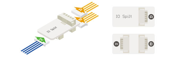
Microduino-IO-split rule1.jpg

After connect the IN interface to one interface of SensorHub, the extended “A port” is corresponding to the “even pins” of SensorHub, and the “B interface” is corresponding to the “odd pins” of SensorHub.

For example, connecting to the 6/7 pin of Hub, the corresponding pin of A is 6/7, and the corresponding pin of B is 7.

Document

Application

It can be used to divide the two IO signals of one 4PIN port in Sensorhub into two 4PIN ports.


Purchase

Gallery

File:Sensor-IO split-F.JPG
Sensor-IO split Front
File:Sensor-IO split -b.JPG
Sensor-IO split Back