8*8 Single-color Lattice Control
Contents[hide]ObjectiveThe course will show you how to use Processing to control 8*8 lattice. Equipment
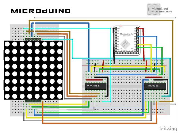
SchematicProgramReferring to ProcessingLattice DebuggingStep 1: Build the hardware environment according to the schematic, as follows:
There will be the code of two ends (Processing and Microduino) needed in this course. Microduino: Using firmata's StandardFirmata program.
//Define the first serial port. arduino = new Arduino(this, Arduino.list()[0], 57600); //Define the output pin in setup() as well as 64 LED objects arduino.pinMode(latchPin, Arduino.OUTPUT);
for (int i=0;i<8;i++) {
for (int j = 0; j < 8; j ++ ) { // Initialize each led and output pin using a for loop.
leds[i][j] = new LED((i+1)*60, (j+1)*60, 50, 50, j+1+(i*10));
     ledStates[i][j]=false;
   }
 }
 background(255);
 for (int i=0; i<8;i++) {
   for (int j = 0; j < 8; j ++ ) { // Run each LED using a for loop.
     leds[i][j].display();
     if (leds[i][j].button) {//switch led on/off
       ledStates[i][j]=true;
     }
     else {
       ledStates[i][j]=false;
     }
   }
 }
//Control and process the 74hc595 chip, map onto the 8*8 lattice. for (int i=0;i<8;i++) {
arduino.digitalWrite(latchPin, 0);
shiftOut(dataPin, clockPin, maskByteLines[0]); //mask(col)
shiftOut(dataPin, clockPin, booleanArray2Byte(ledStates[i])); //row
arduino.digitalWrite(latchPin, 1);
}
Function Reference: mousePressed();//Mouse clicked event processing booleanArray2Byte();//Convert boolean array into byte value shiftOut();//The 74hc595 chip's shifOut binary handler function
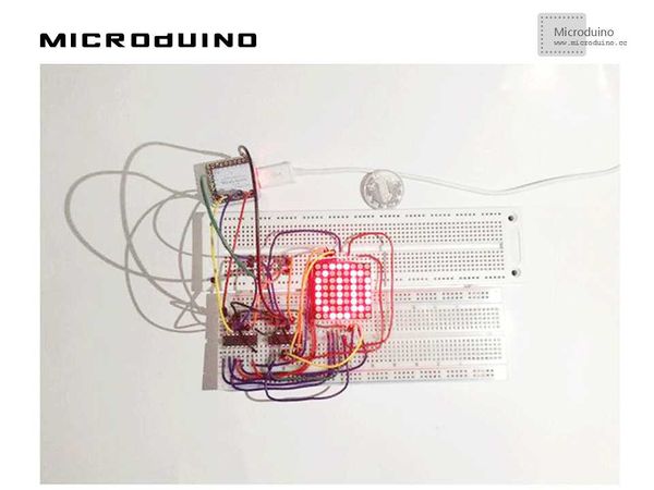
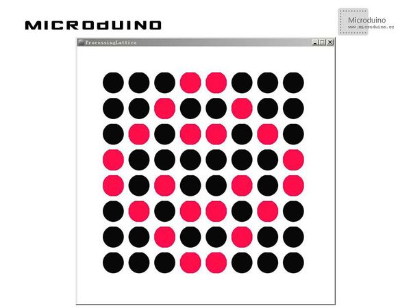
Step 4: The 8*8 LED lattice will be displayed in Processing. Click any LED to see what happens. ResultThe LED lights go on and out correspondingly with the 8*8 lattice, just like this
Video |


