Lesson 12--Microduino 74HC595 Cascade and Serial input Parallel ouput Data
| Language: | English • 中文 |
|---|
Contents[hide]ObjectiveThis tutorial will teach you how to use Microduino to control 74HC595 and display a binary number using 8 LEDs. Equipment
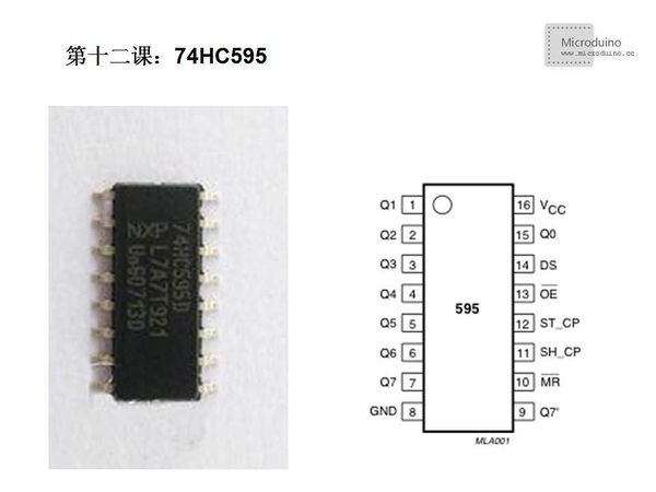
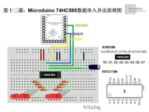
74HC595 74HC595 has eight output pin Q0~Q7 uses to output binary number, mostly use to convert the decimal number to binary number. 74HC595 is the silicon CMOS devices, compatible with low voltage TTL circuit, abide by the JEDEC standard. 74HC595 has a 8 bits shift register and a memory and with three-state output function. Shift register and memory's clock is respectively. Data was input to the shift register at the rising edge of SHcp (the shift register clock input), then input to the storage register (memory) at the rising edge of STcp. If the two clocks connect together, the shift register is always earlier a pulse than the storage register. Shift register has a serial shift input (Ds), a serial output (Q7') and a low level of asynchronous reset. Storage registor has a parallel, three-state bus output. When enabled OE (low level), storage register's data output to the bus. Eight bits serial input/output or parallel output shift register has high resistance off state and three-state function. Turn the serial input 8 digits serial input to parallel output, such as controlling an 8-bit digital tube, there will be no flicker. SchematicProgramDownload program: https://github.com/Microduino/Microduino_Tutorials/tree/master/Microduino_Advanced/Microduino_74HC595 /*
Use the 74HC595 shift register to count from 0 to 255
*/
//Pin 8 connects to 74HC595's ST_CP
int latchPin = 8;
//Pin 12 connects to 74HC595's SH_CP
int clockPin = 12;
////Pin 11 connects to 74HC595's DS
int dataPin = 11;
void setup() {
//Set pins as output
pinMode(latchPin, OUTPUT);
pinMode(clockPin, OUTPUT);
pinMode(dataPin, OUTPUT);
}
void loop() {
//Display binary number in LED, from 0 to 255
for (int numberToDisplay = 0; numberToDisplay < 256; numberToDisplay++) {
//Set latchPin as low leverl
digitalWrite(latchPin, LOW);
//Output decimal number
shiftOut(dataPin, clockPin, MSBFIRST, numberToDisplay);
//Set latch pin as high level, LED will display conrresponding binary nmuber
digitalWrite(latchPin, HIGH);
// pause before next value:
delay(500);
}
}
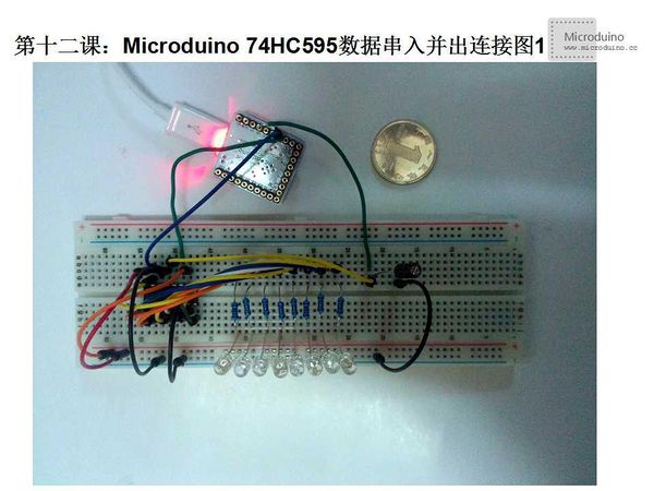
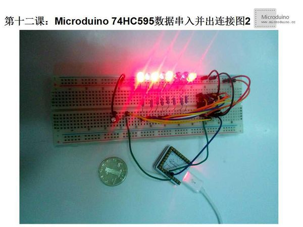
shiftOut(dataPin, clockPin, bitOrder, value) dataPin: dataPin's pin number clockPin: clockPin's pin number bitOrder: Ordered binary code, MSBFIRST(The most significant bit first) or LSBFIRST(The least significant bit first) value: the converted decimal number DebugStep 1: Cope the code to IDE and compile it Step 2: Set up circuit, as follows: Step 3: Run program Step 4: Observe LED Result8 LEDs will display binary number from 0 to 255. On is 1 and off is 0. Video |


