Lesson 13--Microduino "Light alarm (DIY a phototransistor by yourself)"
| Language: | English • 中文 |
|---|
Contents[hide]ObjectiveLED used for indictor and using its the luminous effect, today we tested its another function of the photoelectric effect. The principle is that the LED light-emitting diodes creates a weak electric current in response to a strong light, we can use triode to enlarge it. When the value has changed with buzzer warning. The LED is used to achieve the purpose of the instructions. Equipment
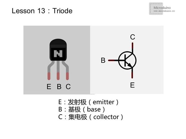
TriodeTriode is semiconductor device used to control current, its role is to amplifier weak signal into radial value larger electrical signals, and switch or voltage follow. Transistor has three poles, respectively called collector C(collector), base B(base),emitter E(emitter). Divided into NPN and PNP two types.
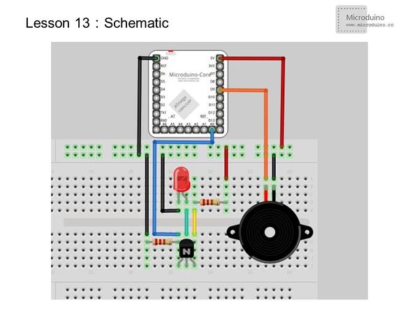
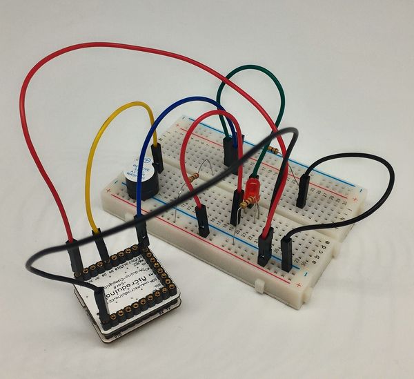
Experimental schematicThis experiment use the voltage following connection that the trigger signal connect the base B, collector C to VCC, and emitter to GND, the output signal through a pulldown resistor to GND. If the base B has a weak current trigger, as the switch is opened, the current flows by C - B - E, emitter E voltage almost equals to the base voltage. The initial state light intensity is not enough, the electric current produced by the photoelectric effect is not enough to trigger, so triode disconnect, directly through the pulldown resistor to pull low voltage. When light intensity increased, the photoelectric effect produced by the electric current triode trigger conduction, but the voltage is very low, so it is difficult to consider the strength of the light, as long as there is voltage change is detected light effect, let the buzzer sound. Programvoid setup()
{
Serial.begin(115200);
}
void loop()
{
int n=analogRead(A0); //Read analog prot data
if(n>0) //The voltage changed,run the following program to generate pulse and let the buzzer sound
{
tone(9, 1000);
delay(100);
noTone(9);
}
Serial.println(n);
delay(10);// Add a delay in serial monitor, otherwise the speed is to fast and esay to crash the system.
}Tone() function
ResultWhen there is a strong light, the buzzer sends dripping sound. DIY a photo triode. Vidoe |


