Lesson 15--Microduino "Make sense of warm cup circuit"
From Microduino Wiki
| Language: | English • 中文 |
|---|
ObjectiveLast lesson introduced how to use LM35D, this lesson will show you how to make a analog thermal cup combined with Microduino. Equipment
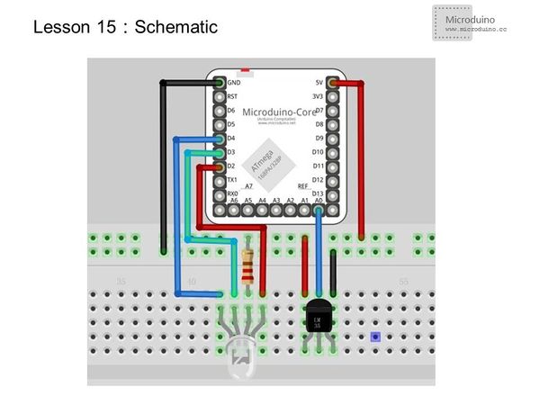
Experimental schematicLM35's connection doesn't change, just add a common anode RGB LED. Programvoid setup() {
Serial.begin(115200); //Set hte baud rate as 115200
for(int i=2;i<5;i++) //Set LED output
{
pinMode(i, OUTPUT);
}
}
void loop() {
int n = analogRead(A0); //Read voltage value from A0 port
float temp = n * (5.0 / 1023.0*100); //Use a float variable to save temperature value which was calculated from voltage.
if (temp<21) //Low temperature setting, and led display
{
digitalWrite(4, HIGH);
digitalWrite(3, HIGH);
digitalWrite(2, LOW);
}
else if (temp>=21 && temp<=23) //Middle temperature setting, && means "and" operation
{
digitalWrite(4, HIGH);
digitalWrite(3, LOW);
digitalWrite(2, HIGH);
}
else if (temp>23) //High temperature setting
{
digitalWrite(4, LOW);
digitalWrite(3, HIGH);
digitalWrite(2, HIGH);
}
Serial.println(temp); //Output the temperature from serial port
delay(1000); //Wait for 1s and refresh the data
}ResultThe temperature is set to low temperature, middle temperature and high temperature three range. When the temperature in the low temperature zone, RGB display a green light, blue light display in the middle temperature zone,and high temperature red light. Simulates a temperature sensing cup. Video |
