Lesson 15--Microduino Digital Tube Experiment 2 - Control Potentiometer
| Language: | English • 中文 |
|---|
Contents[hide]ObjectiveThis lesson will teach use digital tube on Microduino and use potentiometer to control the number display. Find a digital tube library in internet, you can use digital tube easily. You learn how to use the digital tube library and a new function map(). Equipment
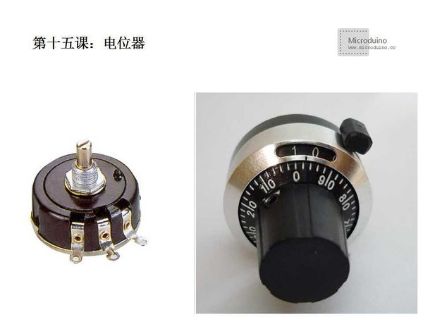
Potentiometer Brief Introduction: Potentiometer is one type of variable resistor. Usually consists of resistance and rotating or sliding system. It uses a contact point moving on resistor to get the voltage output. Function: Adjust the voltage (DB voltage and signal voltage) and current. Structure Characteristics of the Potentiometer: Potentiometer has two fixed end, through the manual adjust rotating shaft or sliding handle, change the position of the moving contact on the resistor, will changed the resistance value between moving contact an one fixed end, and then change the size of the voltage and current.
Potentiometer is a kind of adjustable electronic components. It is consisted by a resistor and a rotating or sliding system. When plus a voltage between two fixed end, by rotating or sliding system to change the location of the contact on the resistor body, between the fixed end and moving contact can get a voltage which has a relationship with the moving contact position. It is mostly used as a divider, then potentiometer is a four-terminal element. Potentiometer basically is a slide rheostat, there are several kinds of style, commonly used in speaker volume switch and laser power size adjustment.
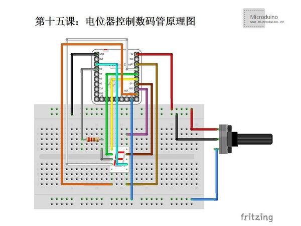
Variable resistor for voltage divider. On the bare resistor body, tightly holding up one or two movable metal contact. Contact position to determine the resistance between both sides and contact resistance. According to the material divides into point line steel, carbon film, solid core wound potentiometer. According to the ratio of output to the input voltage with rotation Angle of the relationship divides into linear potentiometer (linear relationship), function potentiometer (curve). Main parameters are resistance, tolerance, and rated power. Widely used in electronic devices, in sound and receiver for volume control. SchematicPotentiometer has three pins totally, the middle is GND, left and right is power and sigal lines. ProgramDownload program: https://github.com/Microduino/Microduino_Tutorials/tree/master/Microduino_Advanced/MicroduinoDigitalTubeExperiments2 /*
Usage: Microduino drives digital tube and use the potentiometer to adjust value
7 segment digital tube:
A
____
| |
F |____| B
| G |
E |____| C
o DP
D
Pin distribution:
10 9 8 7 6
________
| __ |
| |__| |
| |__|o |
|________|
1 2 3 4 5
* How to connect to Microduino?
* Check the Pin 3 and 9 firstly, generally they are grade-level, the digital tube in kit is common anode, so they both are anode, we can use any of them.
* 1 (E) Connect to Microduino Pin 10
* 2 (D) Connect to Microduino Pin 9
* 3 Because only use one digital tube, so this pin or pin 8 connects to Microduino Pin 5
* 4 (C) Connect to Microduino Pin 8
* 5 (DP) Connect to Microduino Pin 13
* 6 (B) Connect to Microduino Pin 7
* 7 (A) Connect to Microduino Pin 6
* 8 Because only use one digital tube, so this pin or pin 3 connects to Microduino Pin 5
* 9 (F) Connect to Microduino Pin 11
* 10 (G) Connect to Microduino Pin 12
*/
#include "SevSeg.h"
SevSeg sevseg;
void setup() {
//Define the used pin
sevseg.Begin(1,2,3,4,5,6,7,8,9,10,11,12,13);
}
void loop() {
//Enable output function
sevseg.PrintOutput();
int val = analogRead(A0);
val = map(val,0,1023,0,9); //Use the map function do the value mapping
sevseg.NewNum(val, 4); //Digital tube function outputs number, the second parameter is the positon of decimal point. Because it is 4, so won't dispaly decimal point
}DebugFirstly download the library, unzip it and put to libraries folder of Arduino IDE, then restart Arduino IDE to load library. Library link: https://docs.google.com/file/d/0Bwrp4uluZCpNN1Q4dmFZX1MzWVE/edit This library can drive 4bits digital tube and support number, decimal point and easy to use.
Grammar: map(value, fromLow, fromHigh, toLow, toHigh) Parameter: value: need mapped value fromLow: The lower limit of current range value fromHigh: The upper limit of current range value toLow: The lower limit of target range value toHigh:The upper limit of target range value Return value: Return:mapped value In souce code, we used map(val,0,1023,0,9) which means if val in 0-1023, then output value amony 0-9. For example, val is 200, 0-9 to 10 equal, so every one is 102.4. 200 just isn't beyond the range of 204.8, so the output value is 1.
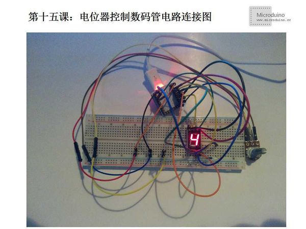
Step 2: Set up circuit, as follows: Step 3: Run program ResultRotate the potentiometer, digital tube will display from 0 to 9. Video |


