Lesson 19--Microduino Two Digital Tube Static Display
| Language: | English • 中文 |
|---|
Contents[hide]ObjectiveThis tutorial will teach you how to use Microduino to measure two digital tube and use two digital tubes to display a double-digit Equipment
SchematicPin Table
Programbyte digit0 = 10; //Ten digits Microduino pin
byte digit1 = 11; //Single digit Microduino pin
byte dotPin = 2; //Decimal point pin
byte sevenSegmentPins[] = {2,3,4,5,6,7,8}; //A,B,C,D,E,F,G Microduino pin
byte sevenSegment[10][7] =
{
//a b c d e f g
{ 0,0,0,0,0,0,1 }, // = 0
{ 1,0,0,1,1,1,1 }, // = 1
{ 0,0,1,0,0,1,0 }, // = 2
{ 0,0,0,0,1,1,0 }, // = 3
{ 1,0,0,1,1,0,0 }, // = 4
{ 0,1,0,0,1,0,0 }, // = 5
{ 0,1,0,0,0,0,0 }, // = 6
{ 0,0,0,1,1,1,1 }, // = 7
{ 0,0,0,0,0,0,0 }, // = 8
{ 0,0,0,1,1,0,0 } // = 9
};
void setup()
{
//Initialize all lights up
pinMode(dotPin, OUTPUT); //pin 2
pinMode(digit0, OUTPUT); //pin 10
pinMode(digit1, OUTPUT); //pin 11
for(int i=0; i<7; i++)
{
pinMode(sevenSegmentPins[i], OUTPUT);
}
digitalWrite(dotPin, HIGH);
digitalWrite(digit0, HIGH);
digitalWrite(digit1, HIGH);
}
//Display number
void segmentWrite(byte digit)
{
byte pin = 2;
for (byte i=0; i<7; ++i)
{
digitalWrite(pin, sevenSegment[digit][i]);
++pin;
}
}
void loop()
{
//Display 68
digitalWrite(digit0, LOW); //Turn off ten digits tube
segmentWrite(8); //Display single digits 8
delay(10); //Delay 10ms
digitalWrite(digit0, HIGH); //Turn on ten digits tube
digitalWrite(digit1, LOW); //Trun off single digits tube
segmentWrite(6); //Display ten digits tube 6
delay(10); //Delay 10ms
digitalWrite(digit1, HIGH); //Turn on single digits tube
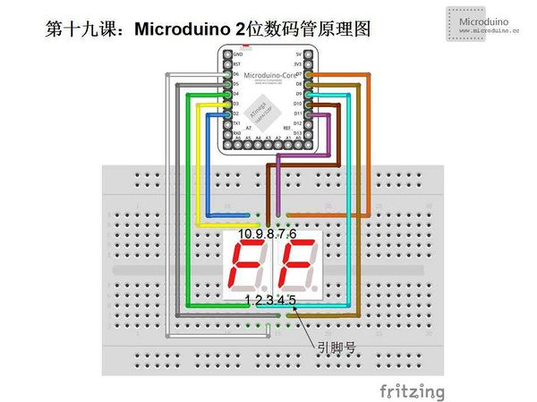
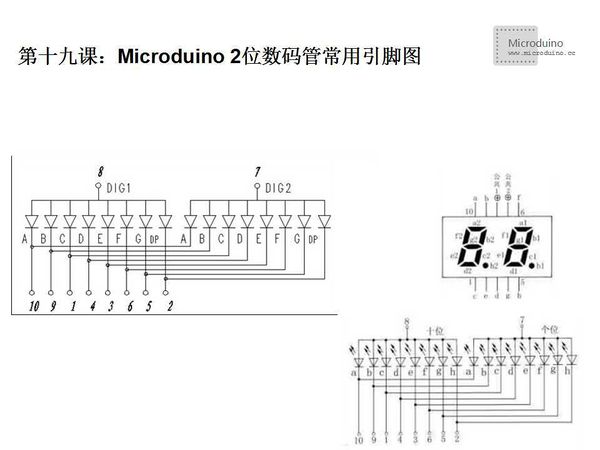
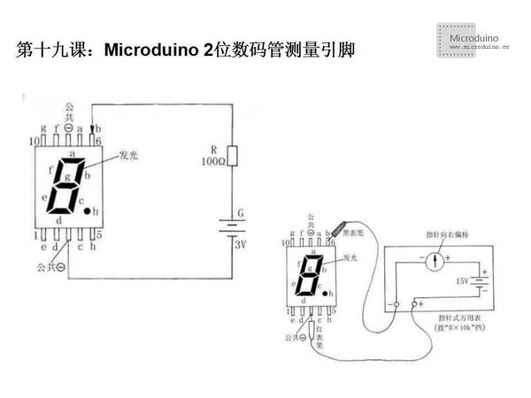
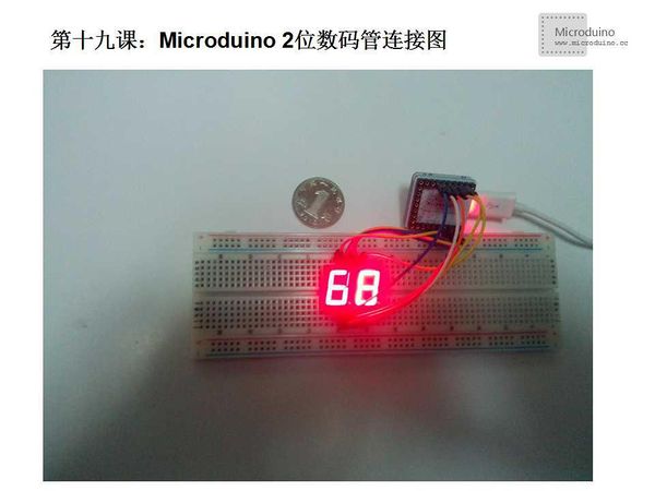
}DebugStep 1: You need to know what the pin definition of the two digital tube that you used. The definition of different manufacturer is different, don't guess it. How to measure the digital tube pin? As well as one digital tube, all digital tube has two types that are common cathode (8 LED cathode sharing a pin) and common anode (8 LED anode sharing a pin), so the two digital tube has two common cathode and common anode pin. Two digital tube pin, as follows: Find common cathode and common anode: Firstly, we find a power supply (3 to 5 v) and 1kΩ (or hundreds of ohm) resistor, VCC concatenated a resistor amd GND connect to arbitrary two pin, there are a lot of combinations, but there is always a LED light, find one is enough, then keep GND connection, VCC one by one touch the left pin, if there are multiple leds (usually 8), that is common cathode. Instead keep VCC connection, GND one by one touch the left foot, if there are multiple leds (usually 8), that is common code. Multimeter or 3 v battery used to test, two digital tube has two selections, bit select and segment select. There are ten pins, as long as connect the pin of the multimeter or 3v battery to the bit select end, another pin connect to segment select end. Detailed information, please refer to the following video. Step 2: Copy the code to IDE and compile it. Step 3: Set up circuit, as follows: Step 4: Run program Step 5: Observe the digital tube ResultDigital tube displays number 68. Video |


