Lesson 25--Microduino & Operational Amplifier-- Inverting Scaling Operation
Contents[hide]PurposeThe tutorial offers the basic knowledge of operational amplifier and this example shows the inverting scaling operation circuit. By changing the resistance value of R1, R2, R3 and R4, you can watch the output result and understand the usage of direction scale operations. EquipmentMicroduino-Core is the 8-bit single-chip development core board with Atmel ATmega328P as the core, which is an open and Arduino Uno compatible controller. Microduino-USBTTL is the program download module, capable of connecting with Microduino-Core or Microduino-Core+ and making the modules communicate with the computer. It uses MicUSB as the download interface, which is also the smallest part of Microduino. Microduino is just as small as a quarter. Besides, the downlaod cable is just like the USB cable of most smart phones, easy to use.
ICL7660ICL7660 is the common negative pressure generation chip. Below is the schematic: S1, S3 and S2, S4 are gang switches, which are switches turning on or turning off at the same time. In the half cycle, S1 and S3 are closed and S2 and S4 are disconnected when voltage Vin charges C1 capacitor. In the other half cycle, S1 and S3 are disconnected and S2 and S4 are closed when C1 charges C2. Since the input electricity of C2 shows negative up and positive down, and the positive end of C2 connects GND, it indicates that the Potential of C2 in the negative terminal is negative. ICL7660 file download:File:ICL7660.pdf SchematicFile:358FritzInvert.jpg 600px LM358 is charged by the dual power. The pin 1 output voltage of LM358 is Vout-pin1=-Vin*(R2/R1). If there is the introduction of -5V power, the pin 1 of the LM358 won’t have negative pressure output. The voltage value can be measured by the multimeter. Vout-pin7=-Vout-pin1(R4/R3), the output voltage of pin 7 is positive, which is recognized by Microduino’s A0 port and can be output in the serial monitor of Arduino IDE. Besides, the output voltage of pin 7 can also be measured by the multimeter. The voltage to ground of the pin 2 and pin 3 in the example is 0V . And the noninverting scaling operation circuit can refer to: [1] The voltage to ground of pin 2 and pin 3 is not 0V. We should know that the voltage of the operational amplifier pin is different in different operation circuit. Program///A0 connect amp358_7 output
///A1 connect single battery output
int anaValueSingleBa; //single battery value map(0--1023)
int anaValueAmp; //amp value map(0--1023)
float anaVoltageSingleBa; //single battery voltage
float anaVoltageAmp; //amp output voltage
void setup()
{
Serial.begin(9600);
}
void loop()
{
anaValueSingleBa=analogRead(A1);
anaVoltageSingleBa=anaValueSingleBa/1023.0*5;
Serial.print("Single battery voltage is ");
Serial.print(anaVoltageSingleBa);
Serial.println("V");
delay(1000);
anaValueAmp=analogRead(A0);
anaVoltageAmp=anaValueAmp/1023.0*5;
Serial.print("Amp358_7 output voltage is ");
Serial.print(anaVoltageAmp);
Serial.println("V");
delay(1000);
}Debugging
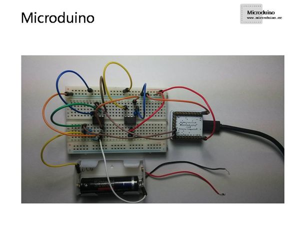
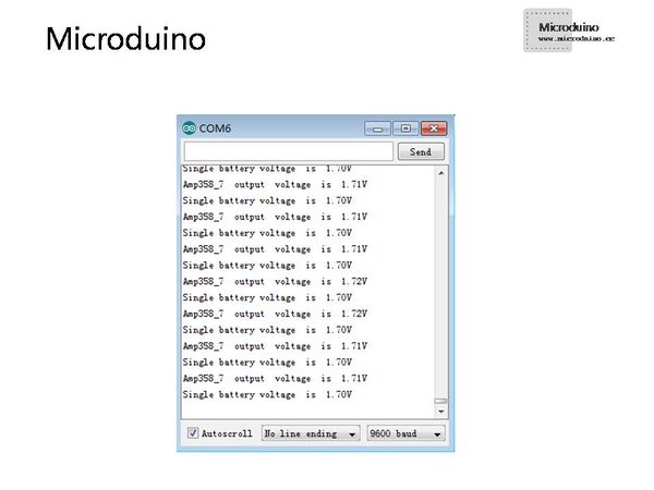
ResultBuild the circuit according to the schematic and you can see the output voltage in the serial monitor of Arduino IDE, then analyze the data. Video |


