Lesson 28--Microduino 8*8 Lattice Transverse Move Display
From Microduino Wiki
| Language: | English • 中文 |
|---|
Contents[hide]ObjectiveWe have learned display a static smiling face, this lesson will teach you transverse move this smiling face. Equipment
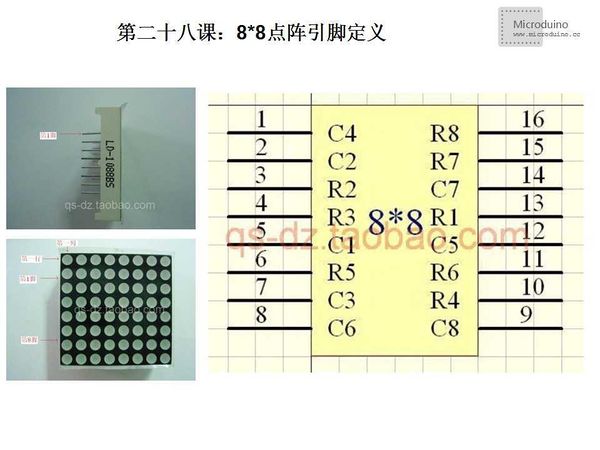
8*8 lattice LED is:LD-1088BS, the following is its pin definition: Schematic
Program//Connect to 74HC595的ST_CP
int latchPin = 8;
//Connect to 74HC595的SH_CP
int clockPin = 12;
//Connect to 74HC595的DS
int dataPin = 11;
//Set the timer
unsigned long time;
//Hide line definition
byte masks[8]={
B01111111,B10111111,B11011111,B11101111,B11110111,B11111011,B11111101,B11111110};
//Definition for smiling face transverse moves
byte rows[4][8]={
{
B00111100,B01000010,B10100101,B10000001,B10100101,B10011001,B01000010,B00111100 }
,
{
B00011110,B00100001,B11010010,B11000000,B11010100,B11001100,B00100001,B00011110 }
,
{
B00001111,B10010000,B11101001,B01100000,B01101010,B01100110,B10010000,B00001111 }
,
{
B10000111,B01001000,B11110100,B00110000,B00110101,B00110011,B01001000,B10000111 }
};
void setup() {
//Set baud rate 9600
Serial.begin(9600);
//Set latchpin as output
pinMode(latchPin, OUTPUT);
}
void loop() {
//Smiling face transverse moves
for(int j=0;j<4;j++) {
unsigned long startTime = millis();
for (unsigned long elapsed=0; elapsed < 1000; elapsed = millis() - startTime) {//Dispaly 600ms
for(int i=0;i<8;i++) {
digitalWrite(latchPin, 0);
shiftOut(dataPin, clockPin, masks[i]); //mask(col)
shiftOut(dataPin, clockPin, rows[j][i]); //row
digitalWrite(latchPin, 1);
}
}
//time=0;
}
}
void shiftOut(int myDataPin, int myClockPin, byte myDataOut) {
// This shifts 8 bits out MSB first,
//on the rising edge of the clock,
//clock idles low
//internal function setup
int i=0;
int pinState;
pinMode(myClockPin, OUTPUT);
pinMode(myDataPin, OUTPUT);
//clear everything out just in case to
//prepare shift register for bit shifting
digitalWrite(myDataPin, 0);
digitalWrite(myClockPin, 0);
//for each bit in the byte myDataOut�
//NOTICE THAT WE ARE COUNTING DOWN in our for loop
//This means that %00000001 or "1" will go through such
//that it will be pin Q0 that lights.
for (i=7; i>=0; i--) {
digitalWrite(myClockPin, 0);
//if the value passed to myDataOut and a bitmask result
// true then... so if we are at i=6 and our value is
// %11010100 it would the code compares it to %01000000
// and proceeds to set pinState to 1.
if ( myDataOut & (1<<i) ) {
pinState= 1;
}
else {
pinState= 0;
}
//Sets the pin to HIGH or LOW depending on pinState
digitalWrite(myDataPin, pinState);
//register shifts bits on upstroke of clock pin
digitalWrite(myClockPin, 1);
//zero the data pin after shift to prevent bleed through
digitalWrite(myDataPin, 0);
}
//stop shifting
digitalWrite(myClockPin, 0);
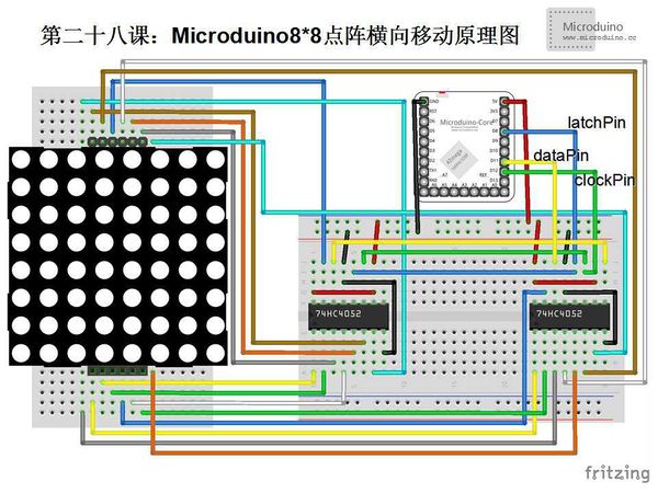
}Define the four transverse move actions in array "byte rows[4][8]" DebugStep 1: Copy the code to IDE and compile it Step 2: Set up circuit: In order to protect the circuit, plus a 220Ω resistor on the every connection line (total 8 lines) between one 74HC595 chip and 8*8 lattice LED. In our example, we don't use the resistor, so the LED's brightness is strong. If the lattice's quality is bad and easily broken. Step 3: Run program
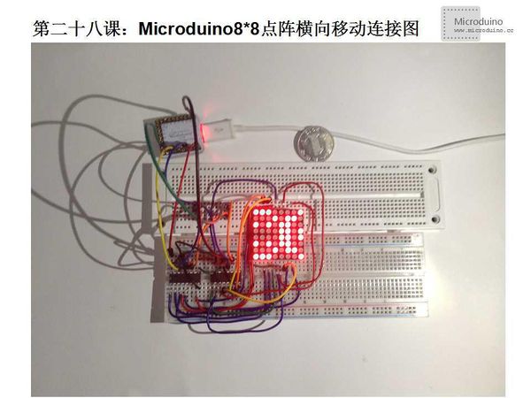
ResultOn 8*8 lattice LED, the smiling face will transverse move. Video |


