Lesson 29--Two Generative Styles of Microduino PWM & Waveform Measurement
Two Generative Styles of Microduino PWM & Waveform Measurement
Contents[hide]PurposeBy this course, we can measure the waveform of Microduino PWM output port. By contrast of PWM output by analogWrite() and the PWM output waveform operated by the register, you'll be able to have an overall understanding of how Microduino outputs PWM. EquipmentMicroduino-Core is the 8-bit single-chip development core board with Atmel ATmega328P as the core, which is an open and Arduino Uno compatible controller. Microduino-USBTTL is the program download module, capable of connecting with Microduino-Core or Microduino-Core+ and making the modules communicate with the computer. It uses MicUSB as the download interface, which is also the smallest part of Microduino. Microduino is just as small as a quarter. Besides, the download cable is just like the USB cable of most smart phones, easy to use.
OscillographOscillograph is a widely used electronic measurement device. It can turn the invisible electrical signal to visible image, easy for people to study various electrical phenomenon change. The X-axis of oscillograph represents time and the Y-axis stands for amplitude. The oscillograph image display in this example adopts CRT, which is old-fashioned. The new oscillograph adopts LCD as the display, which is much smaller than CRT in size and much more powerful in function. SchematicPrinciple Introduction: Microduino-Core adopts Arduino UNO compatible Atmega328p chip, which has much more improvement than MCS-51. Besides, the timer(atmega328p) is more flexible than that with MCS-51 chip, which has prescaler, high-output register added as well as the the ability of outputting PWM directly. By PWM, we can adjust the lightness of the LED as well as motor speed. In Arduino IDE, analogWrite() function can change duty ratio but can not change the frequency of PWM. In addition, the PWM frequency and duty ratio can both be adjustable.
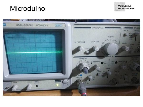
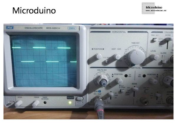
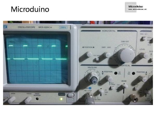
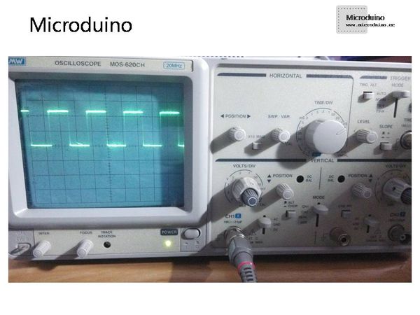
The pin 5 and 6 share the same waveform basically and the oscillograph is 0.5ms/div 2V/div. Check below: Conclusion: The cycle of pin 3, 9, 10 and 11 is around 980Hz and the amplitude is below 5V. If changing the “127” in analogWrite(3,127), you can change the duty ratio based on the frequency. Below is the PWM waveform image. Choose10us/div,2V/div as the oscillograph stall and D10 as the pin output. Another OCR1A=400; OCR1B=200;Measured drawing(10us/div,2V/div) Conclusion: By changing OCR1A, you can easily change the frequency and the cycle of PWM. However, by changing OCR1B, you can easily change the duty ratio under the set OCR1A cycle. Program
void setup()
{
  pinMode(3,OUTPUT);
  pinMode(5,OUTPUT);
  pinMode(6,OUTPUT);
  pinMode(9,OUTPUT);
  pinMode(10,OUTPUT);
  pinMode(11,OUTPUT);
}
void loop()
{
  analogWrite(3,127);
  analogWrite(5,127);
  analogWrite(6,127);
  analogWrite(9,127);
  analogWrite(10,127);
  analogWrite(11,127);
}
void setup()
{
  pinMode(10,OUTPUT);
}
void loop()
{
  TCCR1A =_BV(COM1A0) | _BV(COM1B1) | _BV(WGM11) | _BV(WGM10);
  TCCR1B =_BV(WGM12) |_BV(WGM13) | _BV(CS10);
  // _BV(COM1A0) equal  COM1A0=1,the bit COM1A0 is in the TCCR1A register byte。
  //COM1A0=1; COM1B1=1;enable and choose  the  normal  output,not invert output 。
  // WGM11=1; WGM10=1; WGM12=1; WGM13=1; choose the fast PWM,the top value is OCR1A。OC1B (D10)is the only output pin
  // CS10=1; no prescaling
  OCR1A=400;//change this value can set the frequency   F=16000000/400=40KHz
  OCR1B=100;//change this value can set the duty cycle   Duty=OCR1B/OCR1A
}
Debugging
ResultThe course introduces the output of Microduino PWM. By operating the register, you can adjust PWM waveform cycle and duty ratio. Since changing the related register value of the timer may affect some packed functions of Arduino, the change of the related register value of timer T1 doesn't change the one-second delay time. In the practical application circuit, such as switching power supply circuit, it may need a high-frequency PWM waveform to operate the related register of PWM as required. Video |


