Lesson 37--Microduino Controls Relay
| Language: | English • 中文 |
|---|
Contents[hide]ObjectiveThis tutorial will teach you how to use the relay to control a relatively large current electrical appliances (this experiment will use a driver motor unloaded from the old VCD) Equipment
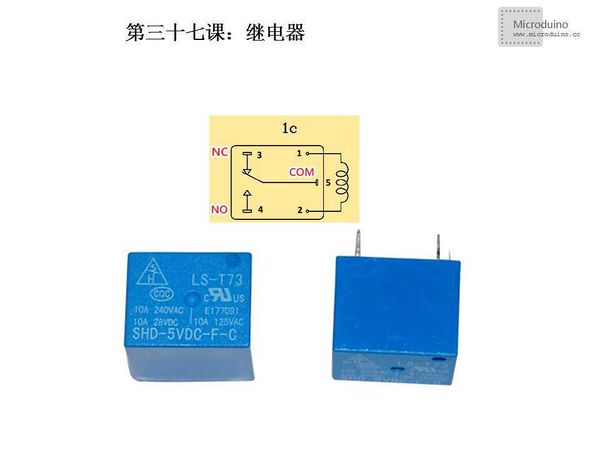
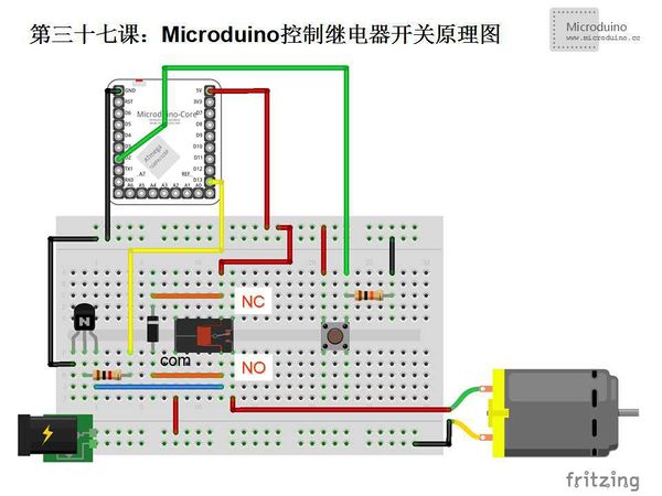
Relay Introduction: Relay is an electronic control device, it has a control system (also called input circuit) and controlled system (also called the output circuit), usually used in automatic control circuit. It is actually a kind of "automatic switch" which uses the less current to control large current. In the circuit, it plays an automatic adjustment, safety protection, conversion circuit function. The principle of relay is that when the input (such as voltage, current, temperature, etc.) achieve specified value, the controlled circuit will be conducted or broken. It can be divided into electric parameters (such as current, voltage, frequency, power, etc.) relay and non-electric parameters (such as temperature, pressure, speed, etc.) relay. It has characters that fast, work stability, long service life, small volume, etc. Widely used in power protection, automation, motor, remote control, measurement and communication device etc. Most of the relay as shown above, there are five pins or 6 pins. This tutorial use the type that has five pins. The difference between them lies in the 6 pins relay has two com pins, you can use any of them freely, and the relay with 5 pins only has on com pin. The following is the relay pin introduction: As shown above in the middle of the yellow diagram, put the bottom pin of relay toward you. NC: Normal Closed NO: Normal Open COM: Common SchematicNote:
Program/*
* Use relay to control motor
*/
const int buttonPin = 2; // pushbutton
const int relayPin = 13; // Relay
int relayState = 0; // relay state
void setup()
{
Serial.begin(9600); // Enable Serial port, set baud rate 9600 bps
pinMode(buttonPin, INPUT); // Set buttonPin to INPUT
pinMode(relayPin, OUTPUT); // Set relayPin to OUTPUT
}
void switchRelay()
{
if (relayState == 0)
relayState = 1; // Set relay state to ON
else
relayState = 0; // Set relay state to OFF
digitalWrite(relayPin, relayState); // Switch the button
Serial.print("Relay status: "); // Serial output relay state
Serial.println(relayState);
}
void loop()
{
int buttonState;
// Read the button state
buttonState = digitalRead(buttonPin);
// Check if the button was pressed
// If yes, buttonState is HIGH
if (buttonState == HIGH) {
switchRelay(); // Switch relay
delay(500); // Delay 0.5s
}
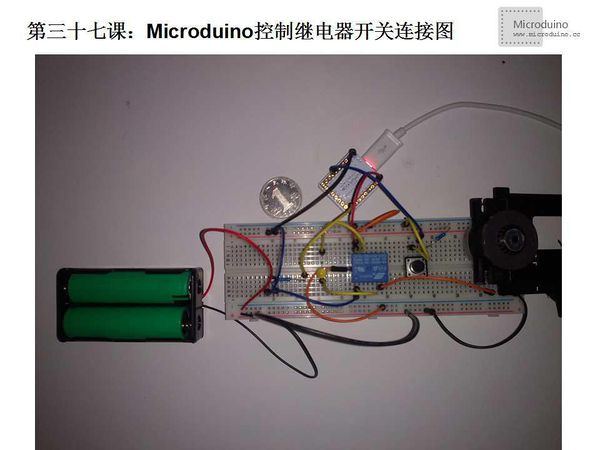
}DebugStep 1: Copy the code to IDE and compile it Step 2: Set up circuit, as follows: Step 3: Run program Step 4: Press button, check if the motor can rotate. ResultPress the button, relay is in Normal Open(NO) state, the motor rotates, then press button again, relay switch to Normal Closed(NC) state, then motor stops. Video |


