Lesson 4--Microduino "LED Brightness and PWM"
From Microduino Wiki
| Language: | English • 中文 |
|---|
Contents[hide]ObjectiveIn the previous three lessons, the LED was either on or off. In this lesson, you will learn how to control an LED's brightness using a button and PWM. PWM stands for pulse width modulation. The circuit adjusts the ratio of digital signals ("0", "1") to create a certain brightness. For example, if there are more 1's (HIGH), then the LED seems brighter. Equipment
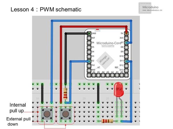
Experiment SchematicOne button is connected using internal pull-up and the other using external pull-down. They are then connected to I/O ports D0~D13. For the Microduino-Core, only D3, D5, D6, D9, D10, and D11 support PWM, so the user must connect the LED to one of those ports. Programint n=0;
void setup ()
{
pinMode(2,INPUT);
pinMode(7,INPUT_PULLUP);//Set to internal pull-up
pinMode(11,OUTPUT);//PWM must use I/O ports 3、5、11、9、10、11
}
void loop()
{
int up =digitalRead(2); //Read port 2's state
int down = digitalRead(7); //Read port 7's state
if (up==HIGH)
{
n=n+5;
if (n>=255) {
n=255;
} //The max limitation is 255
analogWrite(11,n); //Using PWM control the output of port 11, the range of the variable n is 0-255
delay (300);
}
if (down==LOW)
{
n=n-5;
if (n<=0) {
n=0;
}
analogWrite(11,n); //Using PWM control the output of port 11, the range of the variable n is 0-255
delay (300);
}
}AnalogWrite() Usage
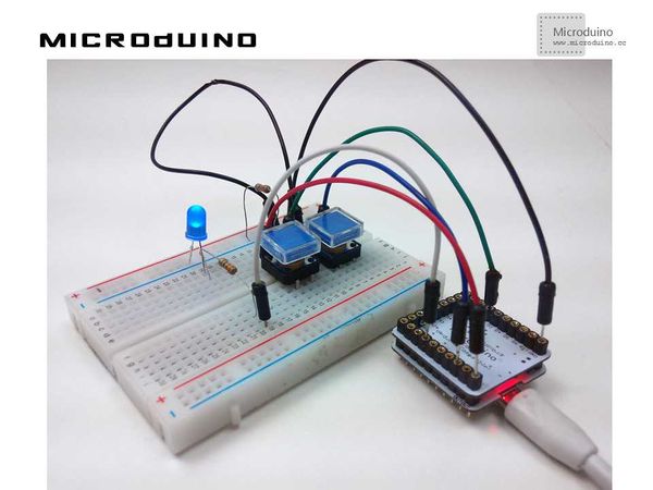
ResultLeft button increases LED brightness and right button decreases LED brightness. Video |


