Lesson 5--Microduino “LED Brightness and Potentiometer PWM”
| Language: | English • 中文 |
|---|
Contents[hide]ObjectiveIn the last lesson, we used a button to generate PWM to control the LED. Now, we will use a precision potentiometer to control the LED. The difference between the two is that a button uses a digital signal (0 and 1) to control the LED. A potentiometer uses an analog signal to generate PWM which is a linear change of state, so the LED's brightness can be changed clearly and gradually. Another downside of using a button is that electronic interference can cause unintended noise. That was why we had to add a pull-up/pull down resistor to our button.
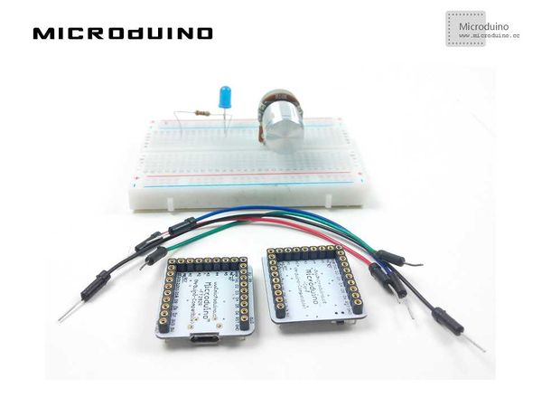
Equipment
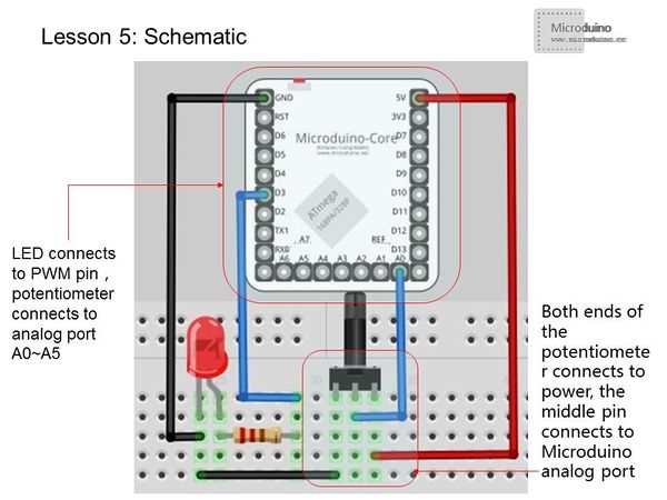
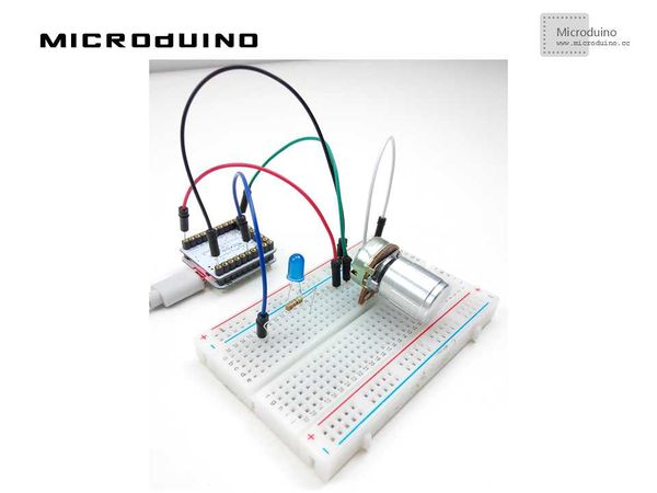
Experiment Schematic
The LED connects to any PWM output pin. The center pin of the potentiometer connects to analog ports A0 ~ A5. The potentiometer's other two pins connect to GND and 5V. The analog interface can measure 0-5V, and analogRead() returns corresponding values 0-1024. Programvoid setup()
{
pinMode(3,OUTPUT); //Choose the PWM output Port
}
void loop()
{
int val= analogRead(A0); //Read the analog port A0's value(voltage range is 0-5V,corresponding value is 0-1204)
val = map(val, 0, 1023, 0, 255);
//We want to map the analog value(0~1024)to(0~255) since the max PWM value is 255.
analogWrite(3, val);
}map() function
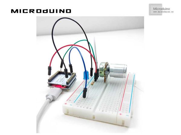
ResultAs you turn the potentiometer, the LED's brightness changes gradually. Video |


