Microduino Dot Matrix Module Displays BMP Colored Image

From Microduino Wiki
Jump to: navigation, search
Language: English  • 中文

Outline

  • Extend the dot matrix screen wiki address and dot matrix library github adress
  • The new dot matrix library adds the function that let the dot matrix able to display bitmaps.
  • The previous bitmap function is limited to single-color bitmap, and needs to take modulus through module software, which is a little convenient.
  • The image format used now is BMP(full name is Bitmap), which is the standard image file format in Windows operating system, and can display colored images.

Bill of Materials

  • Microduino Equipment
Module Number Function
Microduino-Core 1 Core board
Microduino-USBTTL 1 Program download
Microduino-Dot Matrix 4 To display
Microduino-Cube-S1 1 To extend

Principle of the Experiment

  • Typical BMP image file is composed of four parts:
    • Bitmap header file data structure. It contains information such as the type of BMP image file, and the displayed contents;
    • Bitmap information data structure. It contains information such as the width, height, and pressing method of BMP image, and the defined color.
    • Palette. This part is optional. Some bitmaps need palette, and some needn't, such as the true color image(24-bit BMP).
    • Data of the bitmap. This part changes with the bit number of the BMP bitmap. Use RGB directlyin24-bit, and in other less than 24-bit ones, use the color index in the palette.

Because our dot matrix screen is 24-bit, it is natural that I add the bitmap displaying function as 24-bit BMP image. The function is:drawBMP(x,y,data). This function is transplanted on the basis of the spitftbitmap routine of Adafruit. It store the BMP images in Flash store, not occupying much memory space.

Program download

  • Please keep downloading and updating the latest Microduino official IDE.
  • Download the program from the link below: Dot-Matrix-BMP.ino

Operating Instructions

  • Step.1:
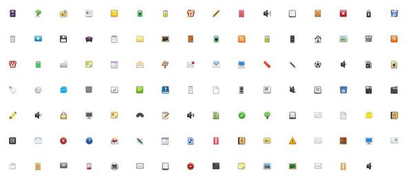
    • At first, let's find a small pictures of material.
    • You can find one in this wedsite:[1]
BMP1.jpg
  • Step.2:
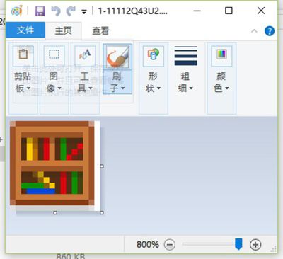
    • Randomly choose one and save it.
    • Open it in drawing tool.
    • Save it as a 24-bit BMP image.
BMP2.jpg
BMP3.jpg


  • Step.3:
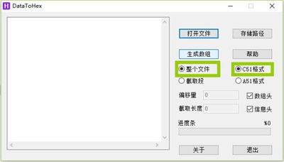
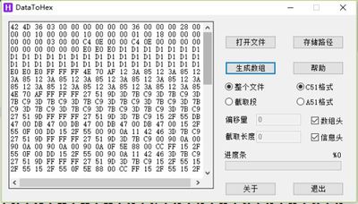
    • Download and open the tool:DataToHex
    • Open the BMP file that you saved.
    • After confirming the two items in the box are chosen correctly, click to generate array.
BMP4.jpg

BMP5.jpg


  • Step.4:
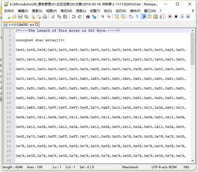
    • Then, open the generated TXT file of the same name in the BMP catalogue.
    • Copy the contents of the array.
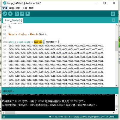
    • Replace the content of BinCode array in the sample program.
    • Download your program to dot matrix(2x2 array).
BMP6.jpg
BMP7.jpg

Programming

  • Stack Microduino-Core and [[Microduino-USBTTL] together.
    • Connect Microduino-USBTTL with USB cable and prepare to upload the program.
    • Note: You'd better upload the program before stacking all the modules.
  • Open Arduino IDE for Microduino environment. (Set-up reference: AVR Core: Getting Started
  • Click 【Tool】, confirm board card (Microduino-Core) and processor(Atmega328P@16M,5V) are chosen correctly, and choose the corresponding port number(COMX).
  • Click 【File】->【Open】, browse to the project program address, and click "Dot-Matrix-BMP.ino" to open it.
  • After all these are correct, click "→" to download the program to the development board.

Code Instruction

#include "Microduino_Matrix.h" 
 
uint8_t Addr[MatrixPix_X][MatrixPix_Y] = { 
  { 64, 63}, 
  { 62, 61} cc
}; 
 
Matrix display = Matrix(Addr); 
 
static const uint8_t BinCode[] PROGMEM = { 
 
}; 
 
void setup(void) { 
  delay(6000); 
  Serial.begin(115200); 
 
  Wire.begin(); 
  display.clearDisplay(); 
  display.drawBMP(0, 0, BinCode); 
} 
 
void loop() { 
}

FAQ