Difference between revisions of "Sound Detection Sensor"
From Microduino Wiki
(→Result) |
|||
| (4 intermediate revisions by 2 users not shown) | |||
| Line 2: | Line 2: | ||
|- | |- | ||
| | | | ||
| − | == | + | ==Outline== |
| + | Sound detection sensor can detect sound intensity but cannot recognize the specified sound. | ||
| + | <br /> | ||
| + | Inside the sensor, there is sound sensitive electret-condenser microphone. Acoustic wave triggers vibration of the thin electret film and causes capacitance change, generating subtle voltage. The voltage is converted to 0-5v, which can be recognized and received by mCookie-CoreUSB. | ||
| − | + | ==Specification== | |
| − | ==Equipment== | + | *Electrical specification |
| − | + | **Operation voltage: 3V~5V | |
| − | + | **Input Device | |
| − | + | *Tech parameters | |
| − | * | + | **Voltage: 0~5V(100Hz~4000Hz) |
| + | **Sound intensity: 45~120dB | ||
| + | **Accuracy:±1% | ||
| + | *Size | ||
| + | **Size of the sensor: 5mm*5mm | ||
| + | **Size of the board: 20mm*20mm | ||
| + | *1.27mm-pith 4PIN interface; | ||
| + | *Connection method | ||
| + | **Output: 0~5V analog signal | ||
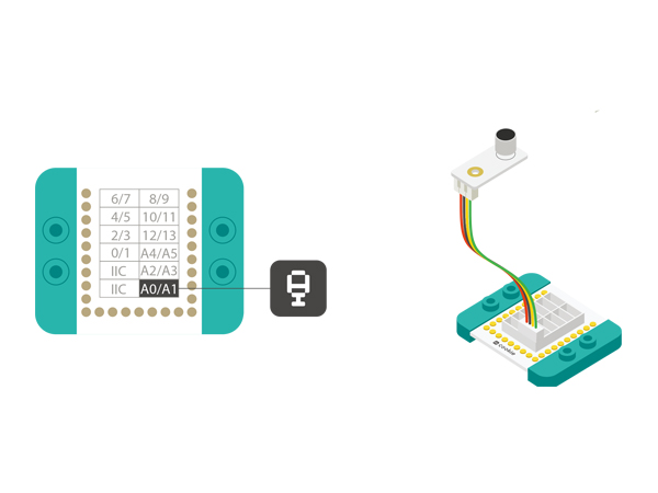
| + | **Pin Description: GND, VCC, signal output and NC(Empty). The output signal is simulated, thus, it needs analog interface to detect(A0-A7). You can connect it to A6,A2,A0 of the Hub. | ||
| + | ==Development== | ||
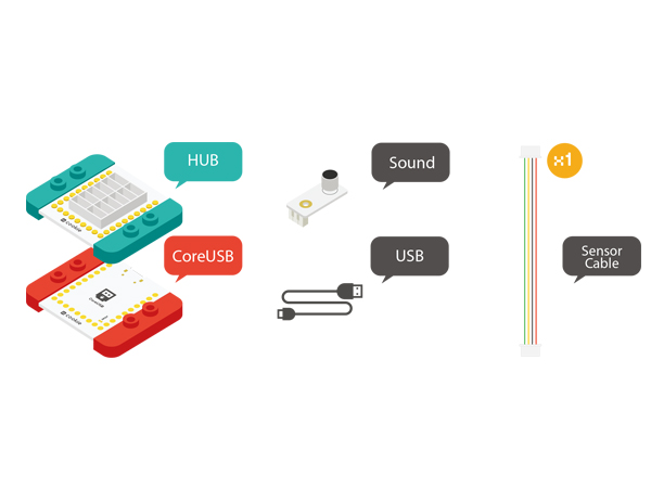
| + | ===Equipment=== | ||
| + | {|class="wikitable" | ||
| + | |- | ||
| + | |Module||Number||Function | ||
| + | |- | ||
| + | |[[mCookie-CoreUSB]]||1||Core board | ||
| + | |- | ||
| + | |[[mCookie-Hub]]||1||Sensor pin board | ||
| + | |- | ||
| + | |[[Microduino-Sound]]||1||Sound detection sensor | ||
| + | |} | ||
| + | *Other Hardware Equipment | ||
| + | **One USB cable | ||
| + | [[File:mic-phone.jpg|600px|center]] | ||
| − | * | + | ===Preparation=== |
| − | * | + | *Setup 1: Connect Microduino-Sound and the A0 analog port of the Hub together. That analog port A0 is the pin of detecting sound. Users can change that according to personal needs. |
| + | [[file:mCookie-Sound-sensor.JPG|600px|center]] | ||
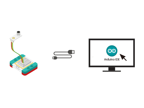
| + | *Setup 2: Stack the CoreUSB, Hub and Sound modules to the computer with a USB cable. | ||
| + | [[file:mCookie-Sound-pc.JPG|600px|center]] | ||
| + | ===Experiment: To Detect Sound Intensity=== | ||
| + | *Open Arduino IDE and copy the following code into the IDE. | ||
| + | <source lang="cpp"> | ||
| + | #define mic_pin A0 | ||
| − | + | int sensorValue; | |
| − | + | // the setup routine runs once when you press reset: | |
| − | + | void setup() { | |
| + | // initialize serial communication at 9600 bits per second: | ||
| + | Serial.begin(9600); | ||
| + | pinMode(mic_pin, INPUT); | ||
| + | } | ||
| − | + | // the loop routine runs over and over again forever: | |
| − | + | void loop() { | |
| + | // read the input on analog pin 0: | ||
| + | sensorValue = analogRead(mic_pin); | ||
| + | // print out the value you read: | ||
| + | Serial.print("Sound:"); | ||
| + | Serial.println(sensorValue); | ||
| + | delay(100); // delay in between reads for stability | ||
| + | } | ||
| + | </source> | ||
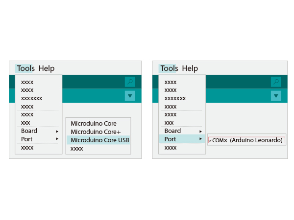
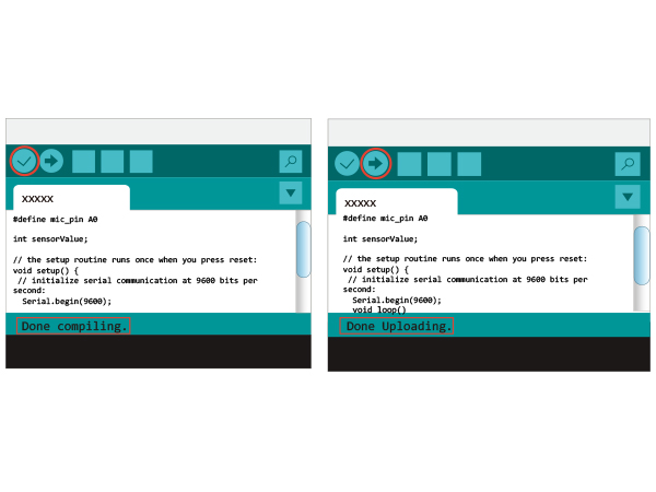
| + | *Choose the right port from Tools→Serial Port in Arduino IDE after compiling. | ||
| + | [[file:uploadsound1.JPG|600px|center]] | ||
| + | *Upload the program directly. | ||
| + | [[file:uploadsound.JPG|600px|center]] | ||
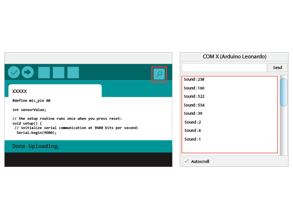
| + | *After the upload, you can open the serial monitor. The displayed value reflects the current sound intensity. | ||
| + | [[file:mCookie-Sound-res-sensor.JPG|600px|center]] | ||
| − | ==Debugging== | + | ===Program Debugging === |
| − | + | *"#define mic_pin A0" defines the pin of controlling LED; A0 means Microduino A0 pin, which can connect to A6, A2, A0. | |
| − | + | *Adopt "analogRead(mic_pin)" to read sound values. | |
| − | |||
| − | |||
| − | |||
| − | |||
| − | |||
| − | |||
| − | |||
| − | |||
| − | |||
| − | |||
| − | |||
| − | |||
| − | |||
| − | |||
| − | |||
| − | |||
==Video== | ==Video== | ||
|} | |} | ||
Latest revision as of 06:36, 30 September 2016
ContentsOutlineSound detection sensor can detect sound intensity but cannot recognize the specified sound.
Specification
DevelopmentEquipment
Preparation
Experiment: To Detect Sound Intensity
#define mic_pin A0

int sensorValue;

// the setup routine runs once when you press reset:
void setup() {
  // initialize serial communication at 9600 bits per second:
  Serial.begin(9600);
  pinMode(mic_pin, INPUT);
}

// the loop routine runs over and over again forever:
void loop() {
  // read the input on analog pin 0:
  sensorValue = analogRead(mic_pin);
  // print out the value you read:
  Serial.print("Sound:");
  Serial.println(sensorValue);
  delay(100);        // delay in between reads for stability
}
Program Debugging
Video |
