Difference between revisions of "Exercise Recorder"
(→Equipment) |
|||
| Line 1: | Line 1: | ||
| − | {{Language| | + | {{Language| Exercise Recorder}} |
{| style="width: 800px;" | {| style="width: 800px;" | ||
|- | |- | ||
| | | | ||
==Objective== | ==Objective== | ||
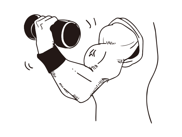
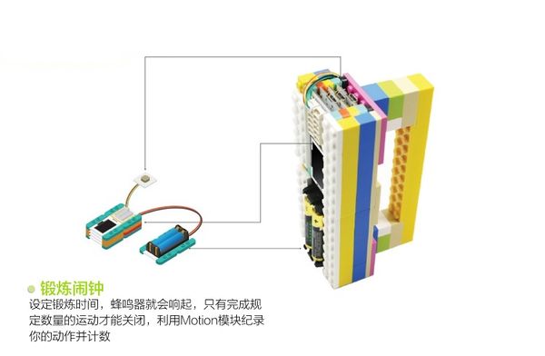
| − | + | You can set exercise time and when it comes to the pre-set time, a buzzer will ring. Only after completing the required times of exercise can the buzzer stop. Here we adopt Microduino-Motion module to record your motion and count. | |
| − | [[File: | + | [[File:Exercise_record-image.jpg|600px|center]] |
| + | |||
| + | ==Principle== | ||
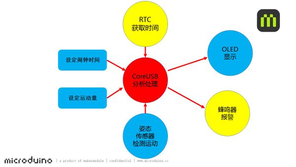
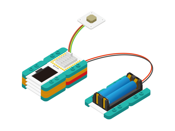
| + | Setting exercise time with Microduino-RTC and when it comes to the pre-set time, a buzzer will ring. Only after completing the required exercise frequency can the buzzer stop. Here we adopt Microduino-Motion module to record your motion and count, and an OLED display module to show the current time and amount of exercise. | ||
| + | [[File:Exercise_record-sch.jpg|600px|center]] | ||
| − | |||
| − | |||
==Equipment== | ==Equipment== | ||
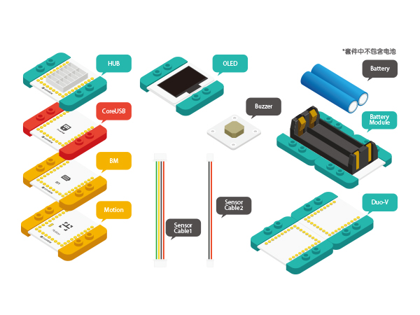
{|class="wikitable" | {|class="wikitable" | ||
|- | |- | ||
| − | |Module||Number||Function | + | |Module||Number||Function |
|- | |- | ||
| − | |[[ | + | |[[mCookie-CoreUSB]]||1||Core board |
|- | |- | ||
| − | |[[ | + | |[[mCookie-Hub]]||1||Sensor pin board |
|- | |- | ||
| − | |[[ | + | |[[mCookie-Motion]]||1||Attitude detection module |
|- | |- | ||
| − | |[[ | + | |[[mCookie-OLED]]||1||Display module |
|- | |- | ||
| − | |[[ | + | |[[mCookie-RTC]]||1||Real time clock |
|- | |- | ||
| − | |[[ | + | | [[mCookie-BM]]||1||Battery management |
|- | |- | ||
| − | | [[ | + | | [[mCookie-Duo-V/]]||1||Extension board |
|- | |- | ||
| − | + | | [[Microduino-Buzzer]]||1||Buzzer sensor | |
| − | |||
| − | | [[Microduino-Buzzer]]||1||Buzzer | ||
|} | |} | ||
| − | + | *Other Equipment | |
| − | *Other Equipment | ||
**One battery | **One battery | ||
| − | ** | + | **LEGO shell |
| − | + | [[File:Exercise_record-module.jpg|600px|center]] | |
| − | == | + | ==Preparation== |
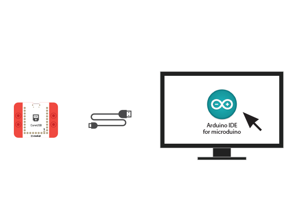
| − | *Setup 1:Connect CoreUSB | + | *Setup 1:Connect the CoreUSB and PC/Mac with a USB cable, open Arduino IDE. |
| − | [ | + | [[Image:CoreUSB_Ble_pc.jpg|600px|center]] |
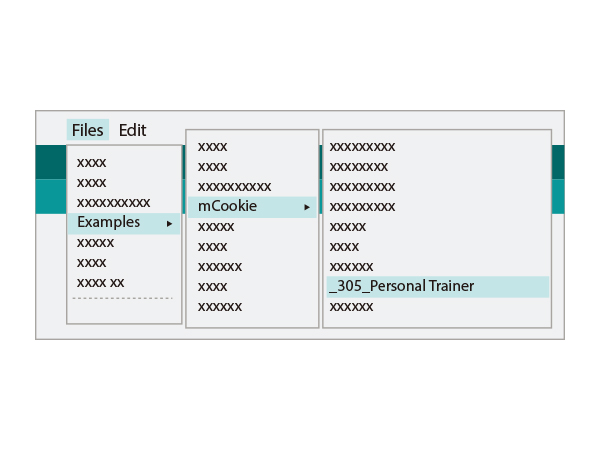
| − | + | *Setup 2:Click Files > Examples > mCookie > _305_PersonalTrainer, upload the program. | |
| − | [ | + | [[File: _305_PersonalTrainer_load.jpg|600px|center]] |
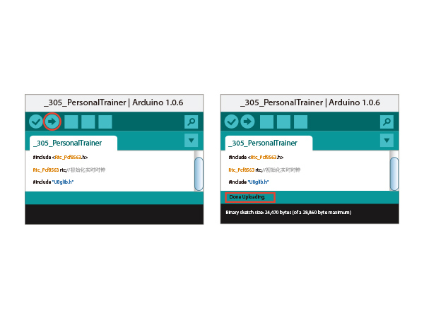
| − | * | + | * Setup 3:Load the code, select the right board and COM port for program download. When it pops up a notice of "Done Uploading", it means the program has been written into the CoreUSB module. |
| − | [[ | + | [[File: _305_PersonalTrainer_load-ok.jpg|600px|center]] |
| − | |||
| − | |||
| − | [[ | ||
==Software Debugging== | ==Software Debugging== | ||
| − | * | + | *Motion detecting |
| − | |||
| − | |||
| − | |||
| − | |||
| − | |||
| − | |||
| − | |||
| − | |||
<source lang="cpp"> | <source lang="cpp"> | ||
| − | + | change_gx = (abs(gx) + abs(gy) + abs(gz)) / 3; | |
| − | + | //Serial.println(change_gx); | |
| − | + | if (change_gx > 80 && !sport_en) | |
| − | + | sport_en = true; | |
| − | + | else if (change_gx <= 10&&!sport_num) | |
| + | { | ||
| + | timer_0 = millis(); | ||
| + | sport_num = true; | ||
| + | } | ||
| + | if (sport_num) | ||
| + | { | ||
| + | if (millis()-timer_0 > 1000) | ||
| + | { | ||
| + | change_gx = (abs(gx) + abs(gy) + abs(gz)) / 3; | ||
| + | if (change_gx <= 10) | ||
| + | { | ||
| + | sport_num= false; | ||
| + | sport_en = false; | ||
| + | timer_0 = millis(); | ||
| + | } | ||
| + | } | ||
| + | } | ||
</source> | </source> | ||
| − | + | *Motion counting | |
| − | * | ||
<source lang="cpp"> | <source lang="cpp"> | ||
| − | + | if (sport_change != sport_en && time_en) | |
| − | |||
| − | |||
| − | |||
| − | |||
| − | |||
{ | { | ||
if (sport_en) | if (sport_en) | ||
{ | { | ||
| − | + | Sport_num -= 1; | |
tone(buzzer_pin, 300); | tone(buzzer_pin, 300); | ||
| − | + | if (Sport_num == 0) | |
| + | { | ||
| + | time_en = false; | ||
| + | noTone(buzzer_pin); | ||
| + | } | ||
} | } | ||
| − | else | + | //else |
| − | + | // noTone(buzzer_pin); | |
| − | + | //Serial.println(sport_en); | |
sport_change = sport_en; | sport_change = sport_en; | ||
} | } | ||
</source> | </source> | ||
| + | * | ||
| + | ==Hardware Buildup== | ||
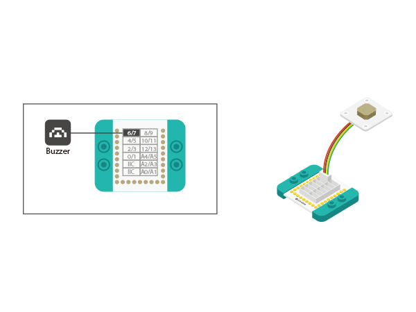
| + | *Setup1:Connect Microduino-Buzzer to the D6 pin of Microduino-Hub. | ||
| + | [[file: Exercise_record_6.jpg |800px|center]] | ||
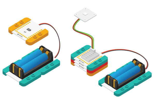
| + | *Setup 2:Connect the activated battery box and the BM module. | ||
| + | [[File:CoreUSB_Ble_steup2.jpg|600px|center]] | ||
| + | *Setup 3:Stack all modules together freely and complete the circuit buildup part. | ||
| + | [[File: Exercise_record _steup3.jpg|600px|center]] | ||
| + | ==Code Debugging== | ||
| + | [[File: Exercise_record _debug1.jpg|600px|center]] | ||
| + | 1.For the first use of Microduino-RTC, you need to set the initial time through programs, find the code section based on the picture above, set according to the local time and load the program into the RTC module through the CoreUSB module. | ||
| + | [[File: Exercise_record _debug2.jpg|600px|center]] | ||
| + | 2.After that, you can add "//" in the front of the code section and the code will turn gray. At this time, please re-load the program into RTC module and then you can record time freely. | ||
| + | [[File: Exercise_record _debug3.jpg|600px|center]] | ||
| + | 3.Find the code section above, set the exercise time, load the code into the CoreUSB module after the setting, you'll find when it comes to this time, the buzzer will go alarm. | ||
| + | [[File: Exercise_record _debug4.jpg|600px|center]] | ||
| + | 4. Find the code section above, set the exercise frequency, load the code into the CoreUSB module after the setting. When the buzzer goes on, the screen will switch to the display of the sports frequency. The buzzer will not stop until you complete the pre-set exercise frequency. | ||
==Result== | ==Result== | ||
| − | + | This project can be used in exercise counting for sit-up, dumbbell lifting and so on. | |
| + | [[File:Exercise_record.jpg|600px|center|excercise]] | ||
==Video== | ==Video== | ||
|} | |} | ||
Revision as of 08:13, 19 January 2016
| Language: | English • 中文 |
|---|
Contents[hide]ObjectiveYou can set exercise time and when it comes to the pre-set time, a buzzer will ring. Only after completing the required times of exercise can the buzzer stop. Here we adopt Microduino-Motion module to record your motion and count. PrincipleSetting exercise time with Microduino-RTC and when it comes to the pre-set time, a buzzer will ring. Only after completing the required exercise frequency can the buzzer stop. Here we adopt Microduino-Motion module to record your motion and count, and an OLED display module to show the current time and amount of exercise. Equipment
Preparation
Software Debugging
change_gx = (abs(gx) + abs(gy) + abs(gz)) / 3;
  //Serial.println(change_gx);
  if (change_gx > 80 && !sport_en)
    sport_en = true;
  else if (change_gx <= 10&&!sport_num)
  {
    timer_0 = millis();
    sport_num = true;
  }
  if (sport_num)
  {
    if (millis()-timer_0 > 1000)
    {
      change_gx = (abs(gx) + abs(gy) + abs(gz)) / 3;
      if (change_gx <= 10)
      {
        sport_num= false;
        sport_en = false;
        timer_0 = millis();
      }
    }
  }
if (sport_change != sport_en && time_en)
  {
    if (sport_en)
    {
      Sport_num -= 1;
      tone(buzzer_pin, 300);
      if (Sport_num == 0)
      {
        time_en = false;
        noTone(buzzer_pin);
      }
    }
    //else
    //  noTone(buzzer_pin);
    //Serial.println(sport_en);
    sport_change = sport_en;
  }
Hardware Buildup
Code Debugging1.For the first use of Microduino-RTC, you need to set the initial time through programs, find the code section based on the picture above, set according to the local time and load the program into the RTC module through the CoreUSB module. 2.After that, you can add "//" in the front of the code section and the code will turn gray. At this time, please re-load the program into RTC module and then you can record time freely. 3.Find the code section above, set the exercise time, load the code into the CoreUSB module after the setting, you'll find when it comes to this time, the buzzer will go alarm. 4. Find the code section above, set the exercise frequency, load the code into the CoreUSB module after the setting. When the buzzer goes on, the screen will switch to the display of the sports frequency. The buzzer will not stop until you complete the pre-set exercise frequency. ResultThis project can be used in exercise counting for sit-up, dumbbell lifting and so on. Video |
