Difference between revisions of "MCookie-Hub"
(→Example) |
(→Example) |
||
| Line 66: | Line 66: | ||
*With an '''[[Sensor-LED|Single Color LED]]''' that is plugged into the '''6/7''' header. Use '''6''' to control the LED. | *With an '''[[Sensor-LED|Single Color LED]]''' that is plugged into the '''6/7''' header. Use '''6''' to control the LED. | ||
| − | Each sensor / trinket page has more specific details to which pins are | + | Each sensor / trinket page has more specific details to which pins are used, but the general rule is use the first signal. |
| − | Each sensor / trinket may require usage of a specific type of pin, such as an analog pin. This information can be | + | Each sensor / trinket may require usage of a specific type of pin, such as an analog pin. This information can be found on the wiki page for that specific sensor / trinket. |
Revision as of 21:49, 29 March 2017
| Language: | English • 中文 |
|---|
|
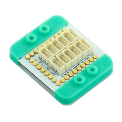
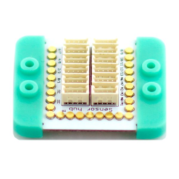
mCookie-Hub is designed for ease of the connection between Microduino Sensor Series and the core modules on the UPIN27 base board as well as further extended experiment. The sensor / trinket connector are 4 pin, 1.25mm pitch JST connectors.
ContentsFeatures
Specification
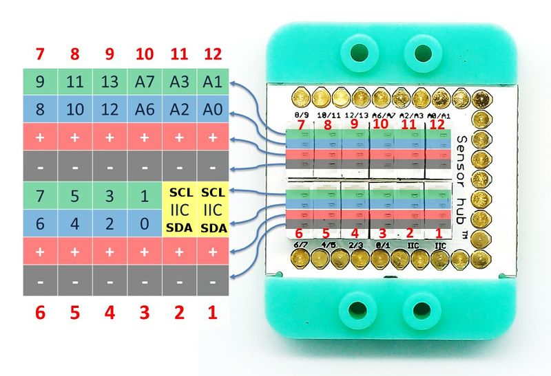
Pin DescriptionMost sensors / trinkets use the first signal (signal 1) when connecting to the sensor hub.
Therefore, when referencing the sensor / trinket in code. Use the first number on the labeled header. In order to use the second signal. An IO splitter is used to split the signals out into two seperate connectors. More can be read about the IO splitter: Sensor-IO_Split Some modules use both the signals 1 & 2, but they are limited. Please refer to the specific sensor / trinket page for more detailed information on a specific one. The IIC (I2C) uses both signals, but these headers are use strictly for IIC communication. Example
Each sensor / trinket page has more specific details to which pins are used, but the general rule is use the first signal. Each sensor / trinket may require usage of a specific type of pin, such as an analog pin. This information can be found on the wiki page for that specific sensor / trinket.
DocumentDevelopment
ProjectPurchaseHistoryPicturesVideo |


