Difference between revisions of "Sensor-Hall"
From Microduino Wiki
(Created page with "{{Language|Microduino-Hall }} {| style="width: 800px;" |- | 400px|thumb|right| Microduino-Hall Microduino-Hall is the Hall sensor module, which ...") |
(→Description of Sensor Pins) |
||
| (13 intermediate revisions by 2 users not shown) | |||
| Line 1: | Line 1: | ||
| − | {{Language| | + | {{Language|mCookieHall }} |
| − | {| style="width: | + | {| style="width: 1000px;" |
| − | | | + | | |
| | | | ||
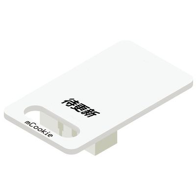
| − | [[File: Microduino-Hall.jpg|400px|thumb|right| | + | [[File: Microduino-Hall.jpg|400px|thumb|right|mCookie-Hall]] |
| + | Product number of mCookie Sensor—Hall:'''MSDS41''' | ||
| + | |||
| + | mCookie Sensor-Hall is a linear hall sensor, which can detect the strength and polarity of the magnetic field. | ||
| − | + | Sensor hall is a magnetic field sensor based on Hall effect. | |
| − | + | Hall effect is a kind of magnetoelectric effect, which is found by Hall(A.H.Hall)on 1879 when he was studying the conduction mechanism of the metal. | |
| Line 13: | Line 16: | ||
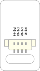
| + | ==Description of Sensor Pins== | ||
| + | {{ST_Pinout | ||
| + | |st_name=Hall Sensor | ||
| + | |pin3=Analog Input | ||
| + | }} | ||
==Features== | ==Features== | ||
| − | * | + | *With high detection sensitivity, and stability. |
| + | *A linear hall sensor with a polarity. | ||
| + | *With small size which is easy to install. | ||
==Specification== | ==Specification== | ||
| − | * | + | *Sensor voltage |
| − | + | **3.3V~5V working voltage | |
| − | **3.3V~5V | ||
| − | |||
| − | |||
| − | |||
| − | |||
| − | |||
| − | |||
| − | |||
| − | * | + | *Size of the sensor |
| − | + | **Size of the board: 23.5mm*13mm; | |
| + | **1.27mm-spacing 4Pin interface connected with sensorhub; | ||
| + | **Sensor CAD drawings: '''[[File:Sensor_CAD.zip]]'''. | ||
| − | [[ | + | *Function description |
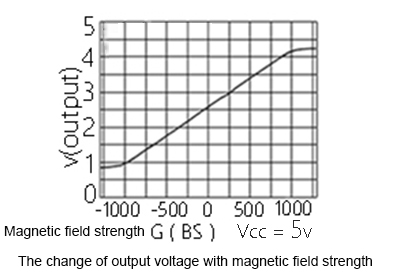
| + | **This sensor is 10-bit ADC(0~1023), and the static value that the pin IO1 gets is 512; | ||
| + | **The strength of the magnetism changes according to south and north poles; | ||
| + | ***If get close to the hall circuit from the back with the N pole, the output voltage will reduce, and the analog value will reduce(512~0), too; | ||
| + | ***If get close with S pole from the back, the output voltage will increase and the analog input value will increase(512~1023), too; | ||
| + | ***If from the front, the output state is opposite to from the back. | ||
| + | <br> | ||
| + | *[[File:Microduino-Hall_xianxingtu.JPG|600px|thumb|left]] | ||
| + | <br style="clear: left"/> | ||
| − | + | *Connection | |
| + | **This sensor can be connected with the following interfaces of the core: '''A0~A7'''. | ||
| − | == | + | ==Documents== |
| − | |||
| − | |||
| + | *Schematic diagram: '''[[File: Microduino_Hall.Zip.pdf]]''' | ||
| + | *HAL49E datasheet: '''[[File: Microduino_Hall_datasheet.pdf]]''' | ||
==Development== | ==Development== | ||
| − | === | + | ===Program Download=== |
| − | * | + | *Download and unzip the program '''[[File:Microduino_Hall_Test.zip]]''' |
| − | |||
| − | |||
| − | |||
| − | |||
| − | |||
| − | |||
| − | |||
| − | [[ | ||
| − | + | ===Programming=== | |
| − | + | {{Upload | |
| − | + | |nameA=[[Microduino-Core]], [[Microduino-USBTTL]] | |
| + | |nameB=[[Microduino-USBTTL]] | ||
| + | |boardName=Microduino/mCookie-Core(328p), Atmega328P@16M,5V | ||
| + | |fileName=Microduino_Hall_Test.ino | ||
| + | }} | ||
| − | ===Hardware | + | ===Hardware Setup=== |
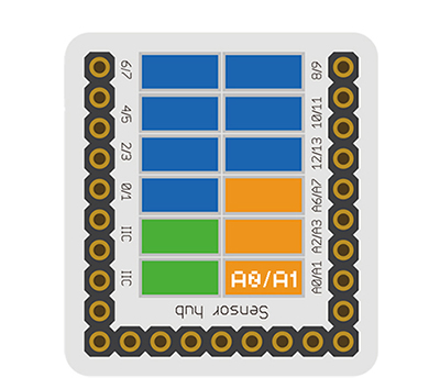
| − | * | + | *Referring to the following picture, connect the Sensor-Hall to the analog interface A0 of '''[[Microduino-Sensorhub]]'''. |
| − | + | <br> | |
| − | + | [[file:Microduino-sensorhub_hall.JPG|thumb|400px|left]] | |
| − | + | <br style="clear: left"/> | |
| − | [[file: | ||
| − | |||
| − | |||
| − | |||
| − | |||
| − | |||
| + | ===Effect Observation=== | ||
| + | *After the download, open the serial port monitor. | ||
| + | *Get close to the hall circuit from the back with S pole. The output voltage of both ends of the hall sensor is during 2.5V~5V, and the analog value it returns is during 512~1023. | ||
| + | *Get close to the hall circuit from the back with the N pole. The output voltage of both ends of the hall sensor is during 2.5V~0V, and the analog value it returns is during 512~0. | ||
| + | *If get close to the circuit from the front, the output state is opposite to from the back. | ||
==Application== | ==Application== | ||
| − | + | *It is suitable for the detection of magnetic field strength. | |
| − | |||
| − | |||
| − | |||
| − | |||
| − | |||
| + | ==Projects== | ||
==Purchase== | ==Purchase== | ||
| Line 82: | Line 86: | ||
==History== | ==History== | ||
| − | == | + | ==Gallery== |
| − | + | {| border="0" cellpadding="10" width="100%" | |
| − | + | |- | |
| − | [[file: Microduino-Hall-F.JPG|thumb| | + | |width="50%" valign="top" align="left"| |
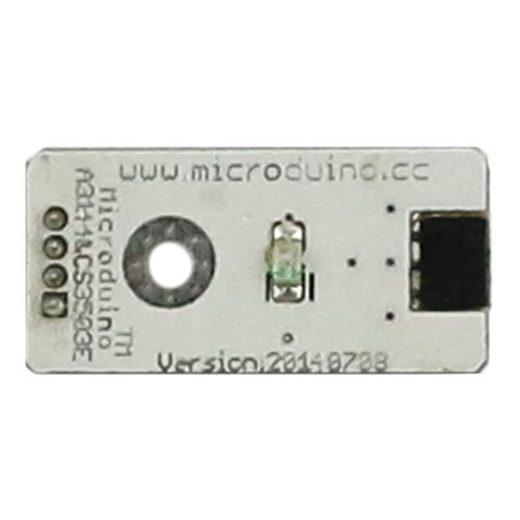
| − | + | [[file: Microduino-Hall-F.JPG|thumb|480px|center|Microduino-Hall Front]] | |
| − | [[file: Microduino-Hall -b.JPG|thumb| | + | |width="50%" valign="top" align="left"| |
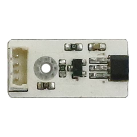
| + | [[file: Microduino-Hall -b.JPG|thumb|480px|center|Microduino-Hall Back]] | ||
| + | |} | ||
|} | |} | ||
Latest revision as of 22:45, 30 March 2017
| Language: | English • 中文 |
|---|
|
Product number of mCookie Sensor—Hall:MSDS41 mCookie Sensor-Hall is a linear hall sensor, which can detect the strength and polarity of the magnetic field. Sensor hall is a magnetic field sensor based on Hall effect. Hall effect is a kind of magnetoelectric effect, which is found by Hall(A.H.Hall)on 1879 when he was studying the conduction mechanism of the metal.
ContentsDescription of Sensor Pins
Features
Specification
Documents
DevelopmentProgram Download
Programming
Hardware Setup
Effect Observation
Application
ProjectsPurchaseHistoryGallery |
