Difference between revisions of "Sensor-IO Split"
From Microduino Wiki
(→Introduction of Pins) |
|||
| (7 intermediate revisions by the same user not shown) | |||
| Line 1: | Line 1: | ||
{{Language|Sensor-IO split }} | {{Language|Sensor-IO split }} | ||
| − | {| style="width: | + | {| style="width: 80%;" |
|- | |- | ||
| | | | ||
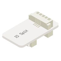
| − | [[File: Microduino-IO-split.jpg| | + | [[File: Microduino-IO-split.jpg|200px|thumb|right| Sensor-IO split]] |
The product number of Sensor-IO Split is: '''MSDE21''' | The product number of Sensor-IO Split is: '''MSDE21''' | ||
| − | Sensor-IO-split can split a 4PIN interface into | + | Sensor-IO-split can split a 4PIN interface (sensor / trinket connector) into two separate connectors. This gives access to the second GPIO on the standard sensor / trinket header. |
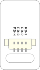
==Introduction of Pins== | ==Introduction of Pins== | ||
| − | {{ | + | {{ST_Pinout |
| − | | | + | |st_name=IO Split |
| − | | | + | |pin3=A |
| − | | | + | |pin4=B |
}} | }} | ||
| − | *All interfaces of Sensor-IO Split are '''1.27mm | + | *All interfaces of Sensor-IO Split are '''4 pin JST 1.27mm pitch connectors / headers'''. |
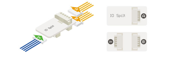
[[File: Microduino-IO-split_rule1.jpg|600px|center]] | [[File: Microduino-IO-split_rule1.jpg|600px|center]] | ||
| − | After | + | After connecting the '''IN connector''' to a header on the Sensor Hub. '''A interface''' corresponds to the '''even pins''' of header, and the '''B interface''' is corresponding to the '''odd pins''' header. |
| − | For example, connecting to the 6/7 pin of Hub, the corresponding pin of A is 6 | + | For example, connecting to the 6/7 pin of Hub, the corresponding pin of A is 6, and the corresponding pin of B is 7. |
==Document== | ==Document== | ||
| Line 33: | Line 33: | ||
==Application== | ==Application== | ||
| − | It can be used to divide the two IO signals of one 4PIN port in | + | It can be used to divide the two IO signals of one 4PIN port in Sensor Hub into two 4PIN ports. |
Latest revision as of 23:32, 12 April 2017
| Language: | English • 中文 |
|---|
|
Sensor-IO-split can split a 4PIN interface (sensor / trinket connector) into two separate connectors. This gives access to the second GPIO on the standard sensor / trinket header. Introduction of Pins
After connecting the IN connector to a header on the Sensor Hub. A interface corresponds to the even pins of header, and the B interface is corresponding to the odd pins header. For example, connecting to the 6/7 pin of Hub, the corresponding pin of A is 6, and the corresponding pin of B is 7. Document
ApplicationIt can be used to divide the two IO signals of one 4PIN port in Sensor Hub into two 4PIN ports.
PurchaseGallery
|


