Difference between revisions of "Lesson 31--Static Display of Chinese Characters on the 16*16 Lattice"
(→Result) |
|||
| (2 intermediate revisions by one other user not shown) | |||
| Line 1: | Line 1: | ||
| − | {{Language| | + | {{Language | 第三十一课--Microduino 16*16点阵汉字静态显示}} |
{| style="width: 800px;" | {| style="width: 800px;" | ||
|- | |- | ||
| | | | ||
| − | |||
==Objective== | ==Objective== | ||
| − | + | Designed for LM-2256 series 16 *16 dot matrix, its size is 40.46*40.46*5mm. The size of each LED lamp is 2.0mm. Using four 74ls595 chips to control it, so you only need three pins to control 256 lights, which is enough to show a Chinese character not only just simple letters or numbers. | |
| − | + | This experiment combines Minroduino modules and the lattice, making it beautiful and compact. | |
==Equipment== | ==Equipment== | ||
*'''[[Microduino-Core]]''' | *'''[[Microduino-Core]]''' | ||
| − | *'''[[Microduino- | + | *'''[[Microduino-USBTTL]]''' |
*Other equipment | *Other equipment | ||
| − | *USB | + | *USB cable |
*LM-2256 16 *16 lattice | *LM-2256 16 *16 lattice | ||
| + | *Pegboard | ||
| + | *Studs, screws | ||
| + | *Welding tools: | ||
| + | **Electric iron | ||
| + | **Solder | ||
| + | **Wire | ||
| + | **Forceps | ||
==Document== | ==Document== | ||
LM-2256 Series 16 *16 matrix displays:'''[[File:.led_16_16.zip]]''' | LM-2256 Series 16 *16 matrix displays:'''[[File:.led_16_16.zip]]''' | ||
| + | ==Features== | ||
| + | *Small, the size is 40.46*40.46*5mm; | ||
| + | *Using 2mm round LED; | ||
| + | *LED lattice screen on a black background, very beautiful; | ||
| + | ==Debug== | ||
| + | ===Welding circuit=== | ||
| + | Step 1: Cut pegboard; | ||
| − | + | Step 2: Design the position of Microduino base plate, then Welding Microduino base plate; | |
| − | + | ||
| − | + | Step 3: Fix the pegboard and lattice, and then plus studs for fixed; | |
| − | + | ||
| + | [[File:Led2256_Circuit_2.jpg|800px|thumb|center|LM-2256]] | ||
| − | + | Step 4: Welding control pin; | |
| − | |||
| − | |||
| − | |||
| − | + | *Pin connection: | |
| − | + | [[File:Led2256_Circuit_3.jpg|800px|thumb|center|LM-2256]] | |
| − | |||
| − | |||
| − | |||
| − | |||
| − | |||
| − | |||
| − | |||
| − | + | *Finished welding | |
| + | [[File:Led2256_Circuit_4.jpg|800px|thumb|center|LM-2256]] | ||
| + | [[File:Led2256_Circuit_5.jpg|800px|thumb|center|LM-2256]] | ||
| + | ===Program=== | ||
| + | *Prepare Work: | ||
| + | **Download test program:'''[[File:.led_16_16_static.zip]]''' | ||
| + | **Modulus software:'''[[File:PCtolCD.zip]]''' | ||
| + | Step 1: Download test program, and then open it; | ||
| + | Step 2: Compile it and then select the board to download, after download, you can see a Chinese character "Ya" (雅); | ||
| − | + | [[File:Led2256_Circuit_6.jpg|800px|thumb|center|LM-2256]] | |
| − | |||
| − | + | Step 3: Change the font; | |
| − | + | Note:'''Change the modulus method to:Determinant, yang code, reverse. After finished, download directly.''' | |
| − | |||
| − | |||
| − | |||
| − | |||
| − | |||
| − | |||
| − | |||
| − | |||
| − | + | Detailed information, please refer to :http://www.microduino.cc/wiki/index.php?title=%E7%AC%AC%E4%BA%8C%E8%AF%BE--Microduino_OLED%E4%BD%BF%E7%94%A8/zh | |
| − | |||
| − | |||
| − | |||
| − | |||
| − | + | [[File:Led2256_Circuit_7.jpg|800px|thumb|center|LM-2256]] | |
| − | |||
| − | |||
| − | |||
| − | |||
| − | |||
| − | |||
| − | |||
| − | |||
| − | |||
==Result== | ==Result== | ||
| − | Through | + | Through the test, it can display a Chinese character statically, and each LED light's brightness is uniform, and beautiful. |
| + | |||
| + | ==Extension== | ||
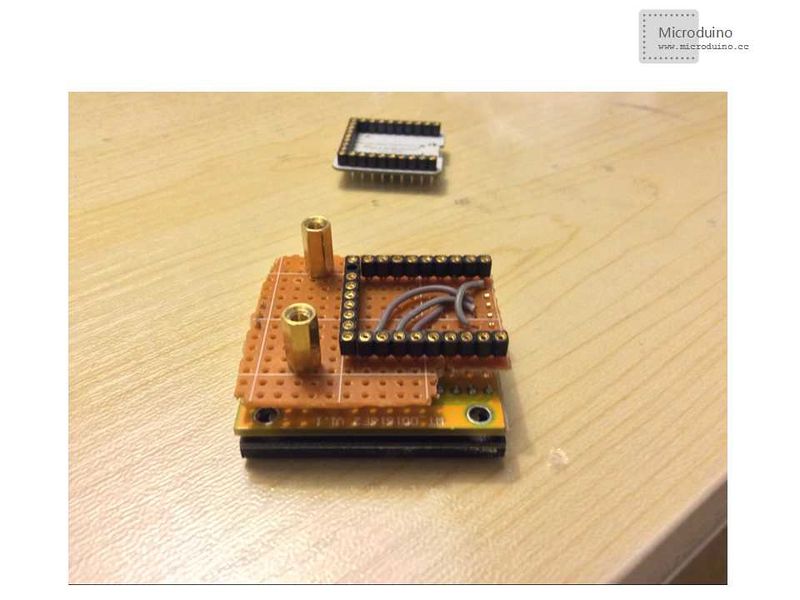
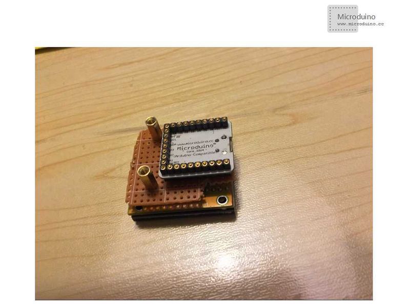
| + | In this experiment, we used Microduino-Core and Microduino Ft232R, thickness is a little big。If use the Microduino-32U4 (Instead Microduino-Core and Microduino Ft232R), the thickness will be decreased. | ||
| − | + | [[File:Led2256_Circuit_8.jpg|800px|thumb|center|LM-2256]] | |
| − | |||
| − | |||
| + | ==Issue need to pay attention== | ||
| + | *When welding microduino base plate, pay attention to pin. After welding, had better measure it using a multimeter, then power on. | ||
| + | *Change the font, need to set modulus format properly. | ||
==Video== | ==Video== | ||
| + | http://v.youku.com/v_show/id_XNjc2MzI1NTMy.html | ||
|} | |} | ||
Latest revision as of 08:44, 12 September 2016
| Language: | English • 中文 |
|---|
ContentsObjectiveDesigned for LM-2256 series 16 *16 dot matrix, its size is 40.46*40.46*5mm. The size of each LED lamp is 2.0mm. Using four 74ls595 chips to control it, so you only need three pins to control 256 lights, which is enough to show a Chinese character not only just simple letters or numbers. This experiment combines Minroduino modules and the lattice, making it beautiful and compact. Equipment
DocumentLM-2256 Series 16 *16 matrix displays:File:.led 16 16.zip Features
DebugWelding circuitStep 1: Cut pegboard; Step 2: Design the position of Microduino base plate, then Welding Microduino base plate; Step 3: Fix the pegboard and lattice, and then plus studs for fixed; Step 4: Welding control pin;
Program
Step 1: Download test program, and then open it; Step 2: Compile it and then select the board to download, after download, you can see a Chinese character "Ya" (雅); Step 3: Change the font; Note:Change the modulus method to:Determinant, yang code, reverse. After finished, download directly. Detailed information, please refer to :http://www.microduino.cc/wiki/index.php?title=%E7%AC%AC%E4%BA%8C%E8%AF%BE--Microduino_OLED%E4%BD%BF%E7%94%A8/zh ResultThrough the test, it can display a Chinese character statically, and each LED light's brightness is uniform, and beautiful. ExtensionIn this experiment, we used Microduino-Core and Microduino Ft232R, thickness is a little big。If use the Microduino-32U4 (Instead Microduino-Core and Microduino Ft232R), the thickness will be decreased. Issue need to pay attention
Video |


