Difference between revisions of "Open Source Smart Bluetooth Lights Illuminator(Somatosensory)"
(→Document) |
|||
| (One intermediate revision by the same user not shown) | |||
| Line 4: | Line 4: | ||
| | | | ||
==Outline== | ==Outline== | ||
| − | * | + | *Project: Open source smart Bluetooth lights illuminator(somatosensory) |
| − | * | + | *Objective: Change attitude through ball rolling to make different colors of light. |
*Difficulty: Medium | *Difficulty: Medium | ||
| − | *Time- | + | *Time-consuming: 2 hours |
| − | * | + | *Maker: |
*Editor in charge: jiale | *Editor in charge: jiale | ||
*Introduction: | *Introduction: | ||
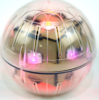
In this tutorial we will use Microduino product module to quickly build a body feeling ball light. | In this tutorial we will use Microduino product module to quickly build a body feeling ball light. | ||
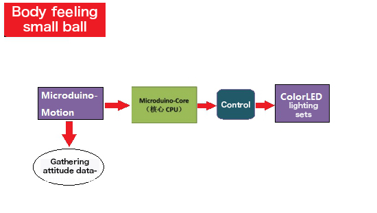
| − | This light gather attitude data through attitude sensor [[Microduino- | + | This light gather attitude data through attitude sensor [[Microduino-Motion]] and reflect on the lamp bank on ColorLED, to make the ball be able change color according to the attitude in the rolling. |
==Bill of Material== | ==Bill of Material== | ||
| Line 53: | Line 53: | ||
==Document== | ==Document== | ||
| − | Body feeling ball | + | Body feeling ball lamp: ['''[[media:Mpu ws2812.zip|The code of the somatosensory ball]]'''] |
Body feeling ball lamp github: [https://github.com/Microduino/mpu_ws2812 MotionBall] | Body feeling ball lamp github: [https://github.com/Microduino/mpu_ws2812 MotionBall] | ||
| Line 59: | Line 59: | ||
==Debugging== | ==Debugging== | ||
Overlay [[Microduino-Core]] and [[Microduino-USBTTL]](no order up and down), and connect them with computer via USB cable. | Overlay [[Microduino-Core]] and [[Microduino-USBTTL]](no order up and down), and connect them with computer via USB cable. | ||
| − | + | Note: Please upload programs before stacking all modules together. | |
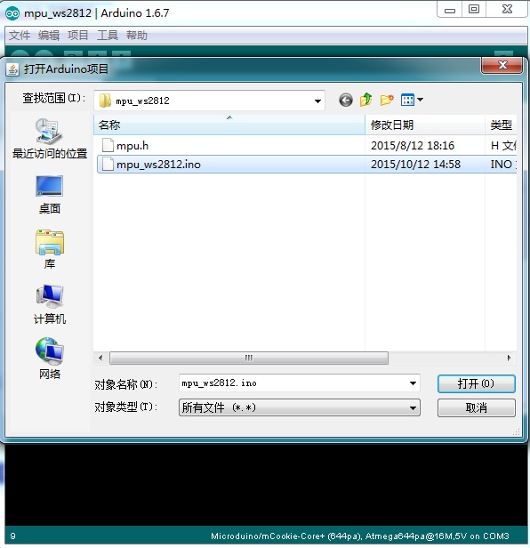
Open Arduino IDE programming software, click [File]->[open], and choose body_welcome.ino after open the folder. | Open Arduino IDE programming software, click [File]->[open], and choose body_welcome.ino after open the folder. | ||
[[File:Motionballdl2.jpg||400px|center]] | [[File:Motionballdl2.jpg||400px|center]] | ||
| − | Click"√", and compile the | + | Click"√", and compile the program. |
Click [Tool], choose board card(Microduino-Core)in board options, select processor(Atmega328p@16M,5V) in processor options, select the right port number in port options, then program directly. | Click [Tool], choose board card(Microduino-Core)in board options, select processor(Atmega328p@16M,5V) in processor options, select the right port number in port options, then program directly. | ||
Click"→", and upload. | Click"→", and upload. | ||
| Line 70: | Line 70: | ||
==Installation== | ==Installation== | ||
*Step1: | *Step1: | ||
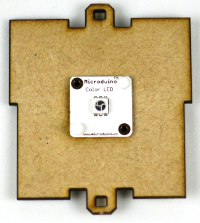
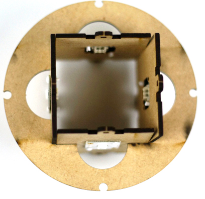
| − | First, use screws to fix Microduino-ColorLED on the side panels(totally | + | First, use screws to fix Microduino-ColorLED on the side panels(totally 6 pieces) |
[[File:Motionballstruct1.jpg||450px|center]] | [[File:Motionballstruct1.jpg||450px|center]] | ||
*Step2: | *Step2: | ||
| Line 81: | Line 81: | ||
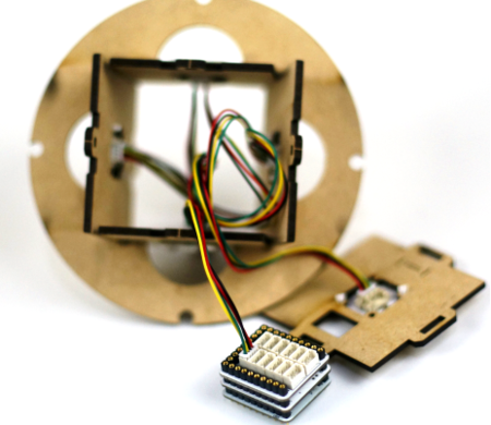
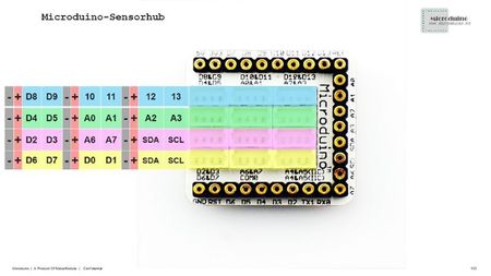
Choose any one ColorLED as the first one, use a sensor cable end to connect the A0/A1 interface of Microduino-Sensorhub, and the other connect the IN interface of ColorLED. | Choose any one ColorLED as the first one, use a sensor cable end to connect the A0/A1 interface of Microduino-Sensorhub, and the other connect the IN interface of ColorLED. | ||
[[File:Motionballstruct5.jpg||450px|center]] | [[File:Motionballstruct5.jpg||450px|center]] | ||
| − | Then continue to use sensor cable to connect to the OUT interface of the first ColorLED and the IN interface of the next ColorLED. The rest can be done in the same manner(OUT of the last one connect to the IN of the next one). First connect the other 5 wooden board except the switch wooden board. Finally, taking ColorLED in the | + | Then continue to use sensor cable to connect to the OUT interface of the first ColorLED and the IN interface of the next ColorLED. The rest can be done in the same manner(OUT of the last one connect to the IN of the next one). First connect the other 5 wooden board except the switch wooden board. Finally, taking ColorLED in the "baseboard" as the penultimate LED, link the interfaces of the IN and OUT with sensor cable, and take the sensor wire of the OUT interface to the opposite through the center of the square, ready to connect to the ColorLED on the wooden switch board. This process is tedious, so you can just seize the core principle that the OUT of the last ColorLED connect to the IN of the next ColorLED. |
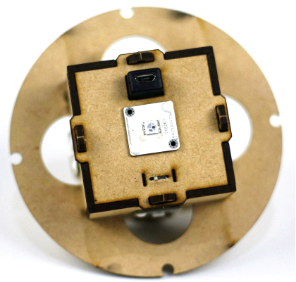
| − | Finally, connect battery to the BM module, make | + | Finally, connect battery to the BM module, make BM stuck with other modules, connect the ColorLED in the wooden switch board to the sensor wire pulled in the baseboard, put all wires, modules, and battery in the square, and cover them. |
[[File:Motionballstruct6.jpg||450px|center]] | [[File:Motionballstruct6.jpg||450px|center]] | ||
Finally put the round plate into the ball, and make the four shrinkage pool corresponding to the four screw hole in the ball. At this time notice that make one side of the switch board corresponding with the side of the ball where a rotating is. Then cove the ball, and tighten with a long screw. | Finally put the round plate into the ball, and make the four shrinkage pool corresponding to the four screw hole in the ball. At this time notice that make one side of the switch board corresponding with the side of the ball where a rotating is. Then cove the ball, and tighten with a long screw. | ||
| Line 90: | Line 90: | ||
Notice that make the switch part upwards, namely, the open direction of hamster ball. | Notice that make the switch part upwards, namely, the open direction of hamster ball. | ||
==Operating Instruction== | ==Operating Instruction== | ||
| − | Connect the lithium battery and cover the wooden board on one side of the switch, then tight screws around hamster ball. Then open the top cap of the hamster ball and turn on the switch, and the surrounding LED lights can light. Changing the angle of the hamster ball , you will see | + | Connect the lithium battery and cover the wooden board on one side of the switch, then tight screws around hamster ball. Then open the top cap of the hamster ball and turn on the switch, and the surrounding LED lights can light. Changing the angle of the hamster ball , you will see lighters' gorgeous color changes. |
==Program Description== | ==Program Description== | ||
Part of the main program | Part of the main program | ||
Latest revision as of 07:39, 13 September 2016
| Language: | English • 中文 |
|---|
ContentsOutline
In this tutorial we will use Microduino product module to quickly build a body feeling ball light. This light gather attitude data through attitude sensor Microduino-Motion and reflect on the lamp bank on ColorLED, to make the ball be able change color according to the attitude in the rolling. Bill of Material
Principle of the ExperimentThe overall system is composed of attitude- gathering part and lights-controlling part. The attitude-gathering part uses Microduino-Motion sensor to get three axis attitude data. Every different angle is corresponding with different value. Then control the change of lights color according to the number obtained. The lights use Microduino-ColorLED, and are connected in series way. Three primary colors of each pixel point can achieve 256 bright to display, and can complete true color display in 16777216 colors, and the scanning frequency is not lower than 400Hz/s.
DocumentBody feeling ball lamp: [The code of the somatosensory ball] Body feeling ball lamp github: MotionBall DebuggingOverlay Microduino-Core and Microduino-USBTTL(no order up and down), and connect them with computer via USB cable. Note: Please upload programs before stacking all modules together. Open Arduino IDE programming software, click [File]->[open], and choose body_welcome.ino after open the folder. Click"√", and compile the program. Click [Tool], choose board card(Microduino-Core)in board options, select processor(Atmega328p@16M,5V) in processor options, select the right port number in port options, then program directly. Click"→", and upload. Installation
First, use screws to fix Microduino-ColorLED on the side panels(totally 6 pieces)
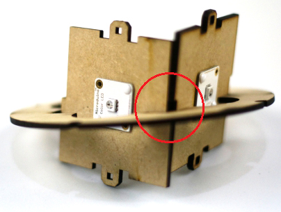
First, put the sides of two side panels upward, and the other two downward.(As the picture 4.6 shows)Note:There is a wide part in the middle of the wooden board to distinguish between upper and lower. According to the way as shown in the picture, put into the circular casing. Separate both sides of the board slightly outward. Then begin to connect the wire of ColorLED的. Choose any one ColorLED as the first one, use a sensor cable end to connect the A0/A1 interface of Microduino-Sensorhub, and the other connect the IN interface of ColorLED. Then continue to use sensor cable to connect to the OUT interface of the first ColorLED and the IN interface of the next ColorLED. The rest can be done in the same manner(OUT of the last one connect to the IN of the next one). First connect the other 5 wooden board except the switch wooden board. Finally, taking ColorLED in the "baseboard" as the penultimate LED, link the interfaces of the IN and OUT with sensor cable, and take the sensor wire of the OUT interface to the opposite through the center of the square, ready to connect to the ColorLED on the wooden switch board. This process is tedious, so you can just seize the core principle that the OUT of the last ColorLED connect to the IN of the next ColorLED. Finally, connect battery to the BM module, make BM stuck with other modules, connect the ColorLED in the wooden switch board to the sensor wire pulled in the baseboard, put all wires, modules, and battery in the square, and cover them. Finally put the round plate into the ball, and make the four shrinkage pool corresponding to the four screw hole in the ball. At this time notice that make one side of the switch board corresponding with the side of the ball where a rotating is. Then cove the ball, and tighten with a long screw. Turn on the switch, then you will see all the lights are lighting, after that, you can roll the ball, then you will see all the LED cool color change. Matters Needing AttentionNotice that make the switch part upwards, namely, the open direction of hamster ball. Operating InstructionConnect the lithium battery and cover the wooden board on one side of the switch, then tight screws around hamster ball. Then open the top cap of the hamster ball and turn on the switch, and the surrounding LED lights can light. Changing the angle of the hamster ball , you will see lighters' gorgeous color changes. Program DescriptionPart of the main program void loop()
{
strip.begin();
strip.show(); // Initialize all pixels to 'off'
getMPU();
colorWipe(strip.Color(Angel_accX, Angel_accY, Angel_accZ), 10);
safe_ms = millis();
}ColorLED control part void colorWipe(uint32_t c, uint8_t wait)
{
for(uint16_t i = 0; i < strip.numPixels(); i++)
{
strip.setPixelColor(i, c);
strip.show();
delay(wait);
}
}video |
