Difference between revisions of "Open Source Smart Socket"
From Microduino Wiki
| (6 intermediate revisions by the same user not shown) | |||
| Line 3: | Line 3: | ||
| | | | ||
==Outline== | ==Outline== | ||
| − | * | + | *Project: Microduino open source smart socket (ESP8266connect with Blynk) |
| − | * | + | *Objective: Mobile phone remote control socket on and off. |
| − | * | + | *Difficulty: Low |
| − | *Time- | + | *Time-consuming: 2 hours |
| − | * | + | *Maker: ray |
*Introduction: | *Introduction: | ||
| − | **The user can use | + | **The user can use mobile phone to surf the Internet to connect with Blynk control the Internet of things. |
**The core control module [[Microduino-Core+]] controls the relay switch after receiving introductions. | **The core control module [[Microduino-Core+]] controls the relay switch after receiving introductions. | ||
| − | **WiFi wireless module [[Microduino-WIFI | + | **WiFi wireless module [[Microduino-WIFI(ESP)]] is responsible for wireless communications. |
[[File:outletImg.png||600px|center]] | [[File:outletImg.png||600px|center]] | ||
| Line 30: | Line 30: | ||
|[[Microduino-USBTTL]] ||1||Program download | |[[Microduino-USBTTL]] ||1||Program download | ||
|- | |- | ||
| − | |[[Microduino-WIFI | + | |[[Microduino-WIFI(ESP)]] ||1||Network connection |
|} | |} | ||
| Line 54: | Line 54: | ||
==Principle of the Experiment== | ==Principle of the Experiment== | ||
| − | *Principle of the | + | *Principle of the Circuit's Control |
*The socket has two main components on the control panel. | *The socket has two main components on the control panel. | ||
| − | **''' Switching mode power supply''' | + | **''' Switching mode power supply''': Change 220V city power into 5V working voltage to supply Microduino module with power. |
| − | **'''Relay''' | + | **'''Relay''': Microduino module switch control the socket through it. |
*The socket can pick up any electrical appliances.'''(<1250W)''' | *The socket can pick up any electrical appliances.'''(<1250W)''' | ||
| Line 63: | Line 63: | ||
*It is actually a smart switch which can use weak electricity to control strong electricity. | *It is actually a smart switch which can use weak electricity to control strong electricity. | ||
*Principle of Wireless Communication | *Principle of Wireless Communication | ||
| − | **Use '''[[Microduino-WIFI | + | **Use '''[[Microduino-WIFI(ESP)]]''' WiFi communication module to connect with the wide area network. |
**Use Blynk APP to communicate through Blynk server. | **Use Blynk APP to communicate through Blynk server. | ||
| Line 101: | Line 101: | ||
|width="50%" valign="top" align="left"| | |width="50%" valign="top" align="left"| | ||
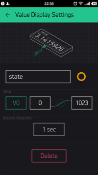
*Select '''Value Display''', and input state to show this control is used to obtain the state of the socket switch. | *Select '''Value Display''', and input state to show this control is used to obtain the state of the socket switch. | ||
| − | *'''INPUT''' selects V0, and '''READING FREQUENCY''' select | + | *'''INPUT''' selects V0, and '''READING FREQUENCY''' select 1s to show the frequency of the socket to send state. |
|width="50%" valign="top" align="left"| | |width="50%" valign="top" align="left"| | ||
[[File:BlynkSettingOutlet4.png||200px|center]] | [[File:BlynkSettingOutlet4.png||200px|center]] | ||
| Line 157: | Line 157: | ||
==Program Download== | ==Program Download== | ||
| − | Smart Socket | + | Smart Socket Github: [https://github.com/Microduino/ESP8266BlynkOutlet ESP8266BlynkOutlet] |
==Programming== | ==Programming== | ||
*Overlay '''[[Microduino-Core+]]''' and '''[[Microduino-USBTTL]]''' together. | *Overlay '''[[Microduino-Core+]]''' and '''[[Microduino-USBTTL]]''' together. | ||
**Connect '''[[Microduino-USBTTL]]''' with USB cable and prepare to upload programs. | **Connect '''[[Microduino-USBTTL]]''' with USB cable and prepare to upload programs. | ||
| − | ** | + | **Note: Please upload programs before stacking all modules together. |
*Open Arduino IDE for Microduino environment. (The reference to set up:'''[[AVR Core:Getting started]]''') | *Open Arduino IDE for Microduino environment. (The reference to set up:'''[[AVR Core:Getting started]]''') | ||
*Click '''[Tool]''' bar, confirm '''board card(Microduino-Core+) processor(Atmega644pa@16M,5V)''' selected correctly, and choose the corresponding '''port number(COMX)''' | *Click '''[Tool]''' bar, confirm '''board card(Microduino-Core+) processor(Atmega644pa@16M,5V)''' selected correctly, and choose the corresponding '''port number(COMX)''' | ||
| − | *Click '''[File]'''->'''[Open]''', browse to the project program address, and click ''' | + | *Click '''[File]'''->'''[Open]''', browse to the project program address, and click '''"ESP8266BlynkOutlet.ino"''' program to open it. |
*After all these are correct, click '''"→"''' button to download to the development board. | *After all these are correct, click '''"→"''' button to download to the development board. | ||
| Line 173: | Line 173: | ||
|width="50%" valign="top" align="left"| | |width="50%" valign="top" align="left"| | ||
*'''Step1''' | *'''Step1''' | ||
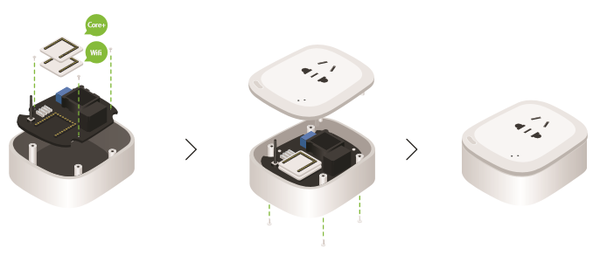
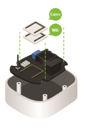
| − | **First, use three '''4mm screws''' to fix the circuit board on the bottom case, then prepare '''[[Microduino-WIFI | + | **First, use three '''4mm screws''' to fix the circuit board on the bottom case, then prepare '''[[Microduino-WIFI(ESP)]]''' and '''[[Microduino-Core+]]'''. |
|width="50%" valign="top" align="left"| | |width="50%" valign="top" align="left"| | ||
[[File:Chazuo1v1.png||200px|center]] | [[File:Chazuo1v1.png||200px|center]] | ||
| Line 182: | Line 182: | ||
|width="50%" valign="top" align="left"| | |width="50%" valign="top" align="left"| | ||
*'''Step2''' | *'''Step2''' | ||
| − | **Overlay '''[[Microduino-WIFI | + | **Overlay '''[[Microduino-WIFI(ESP)]]''' and '''[[Microduino-Core+]]''' on the baseboard of the smart socket. |
|width="50%" valign="top" align="left"| | |width="50%" valign="top" align="left"| | ||
[[File:Chazuo2v1.png||200px|center]] | [[File:Chazuo2v1.png||200px|center]] | ||
| Line 192: | Line 192: | ||
|width="50%" valign="top" align="left"| | |width="50%" valign="top" align="left"| | ||
*'''Step3''' | *'''Step3''' | ||
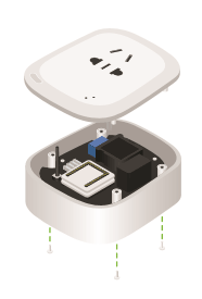
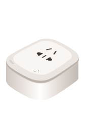
| − | **Make the smart socket shell buckle into the pan, use a ''' | + | **Make the smart socket shell buckle into the pan, use a '''8mm-long screw''' to screwing in, and fix the top and bottom cases. Now the smart socket part has been set up completely. |
|width="50%" valign="top" align="left"| | |width="50%" valign="top" align="left"| | ||
[[File:Chazuo3v1.png||200px|center]] | [[File:Chazuo3v1.png||200px|center]] | ||
| Line 204: | Line 204: | ||
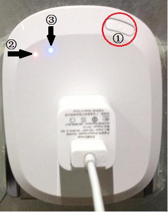
*Insert any electric power cord in the home into the smart socket, such as the electric power cord of the television, the refrigerator, and the humidifier. | *Insert any electric power cord in the home into the smart socket, such as the electric power cord of the television, the refrigerator, and the humidifier. | ||
*Here we take the phone charger for example, and inset it into the smart socket. | *Here we take the phone charger for example, and inset it into the smart socket. | ||
| − | *Open the Blynk client and press the switch button, you will see the indicator lights up, and | + | *Open the Blynk client and press the switch button, you will see the indicator lights up, and then it start charging the mobile phone. |
| − | In the | + | In the picture: |
① is the switch button. | ① is the switch button. | ||
② is the power indicator light. | ② is the power indicator light. | ||
| Line 215: | Line 215: | ||
==Attention Problem== | ==Attention Problem== | ||
*Contacting with the electricity is very dangerous, so pay attention to safety! | *Contacting with the electricity is very dangerous, so pay attention to safety! | ||
| − | *All installation operation | + | *All installation operation can't be processed with power! |
*After the installation and the jump, even intelligent socket is closed, you must not touch the power switch! | *After the installation and the jump, even intelligent socket is closed, you must not touch the power switch! | ||
== FAQ== | == FAQ== | ||
Latest revision as of 06:26, 30 September 2016
ContentsOutline
Bill of Materials
Principle of the Experiment
Obtain, and Configure Blynk
Get the Mobile Client of Blynk
Program DownloadSmart Socket Github: ESP8266BlynkOutlet Programming
Assemble the Smart Socket
Operating Introduction
Attention Problem
FAQ |
