Difference between revisions of "Fortune Cat"
(→Schematic) |
|||
| (7 intermediate revisions by 3 users not shown) | |||
| Line 4: | Line 4: | ||
| | | | ||
==Overview== | ==Overview== | ||
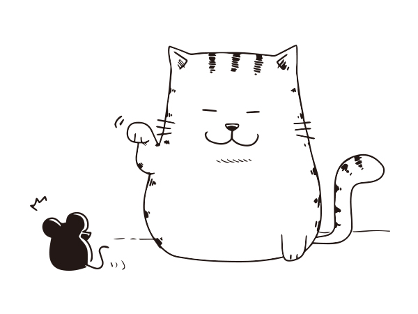
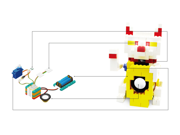
| − | When | + | When you pass by, the Fortune Cat will wave to you with two eyes shining and meow. |
| − | |||
| − | to you | ||
[[File: MicroduinoFortuneCat-stater.jpg|600px|center]] | [[File: MicroduinoFortuneCat-stater.jpg|600px|center]] | ||
| Line 23: | Line 21: | ||
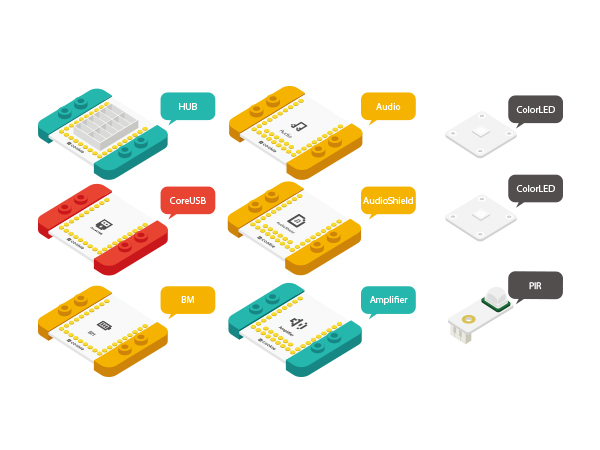
|Module||Number||Function | |Module||Number||Function | ||
|- | |- | ||
| − | |[[mCookie-CoreUSB | + | |[[mCookie-CoreUSB]]||1||Core board |
|- | |- | ||
| − | |[[mCookie-Hub | + | |[[mCookie-Hub]]||1||sensor hub board |
|- | |- | ||
| − | |[[Microduino-TOUCH | + | |[[Microduino-TOUCH]]||1||touch sensor |
|- | |- | ||
| − | |[[Microduino-PIR | + | |[[Microduino-PIR]]||1||PIR sensor |
|- | |- | ||
| − | |[[mCookie-Audio | + | |[[mCookie-Audio]]||1||Audio module |
|- | |- | ||
| − | |[[mCookie-Amplifier | + | |[[mCookie-Amplifier]]||1||Power Amplifier module |
|- | |- | ||
| − | |[[Microduino- | + | |[[Microduino-Colored LED]]||2||led light |
|- | |- | ||
| − | | [[mCookie-BM | + | | [[mCookie-BM]]||1||Battery Management |
|- | |- | ||
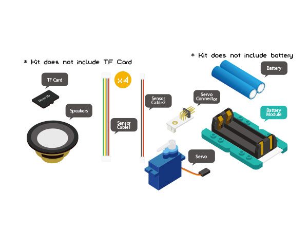
| Servo||1||Servo | | Servo||1||Servo | ||
| Line 43: | Line 41: | ||
|} | |} | ||
[[File: MicroduinoFortuneCat-module.jpg|600px|center]] | [[File: MicroduinoFortuneCat-module.jpg|600px|center]] | ||
| − | [[File: MicroduinoFortuneCat-module1.jpg|600px| | + | [[File: MicroduinoFortuneCat-module1-E.jpg|600px| |
center]] | center]] | ||
| Line 52: | Line 50: | ||
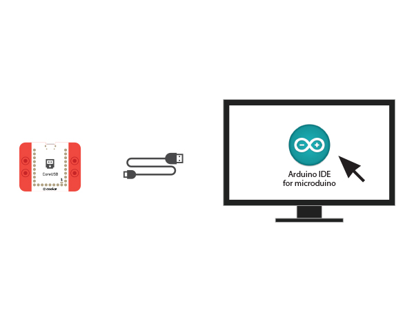
and then start the Arduino IDE. | and then start the Arduino IDE. | ||
[[File:CoreUSB_Ble_pc.jpg|600px|center]] | [[File:CoreUSB_Ble_pc.jpg|600px|center]] | ||
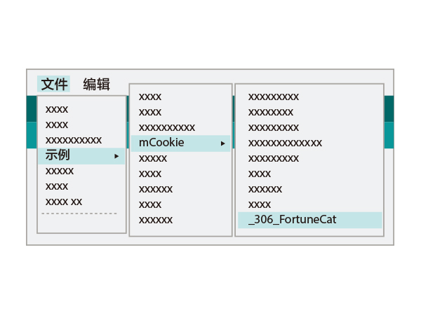
| − | *Setup | + | *Setup 2:Click Files > Examples > mCookie > |
_303_FortuneCat. | _303_FortuneCat. | ||
| Line 62: | Line 60: | ||
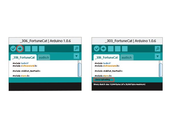
successfully been uploaded into the CoreUSB. | successfully been uploaded into the CoreUSB. | ||
[[File: _303_FortuneCat -com.jpg|600px|center]] | [[File: _303_FortuneCat -com.jpg|600px|center]] | ||
| + | |||
==Program description== | ==Program description== | ||
*Control pin definitions | *Control pin definitions | ||
| Line 97: | Line 96: | ||
module. | module. | ||
[[file: MicroduinoFortuneCat2-hub.JPG|600px|center]] | [[file: MicroduinoFortuneCat2-hub.JPG|600px|center]] | ||
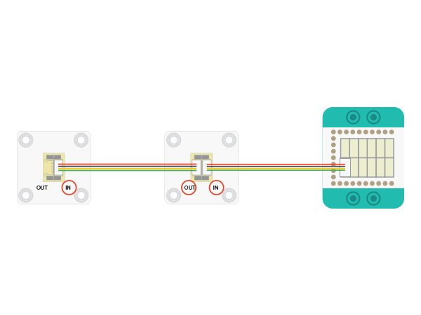
| − | To connect | + | To connect multiple LEDs in a series, follow the above |
diagram. Notice that the sensor cable connects to the IN | diagram. Notice that the sensor cable connects to the IN | ||
| Line 122: | Line 121: | ||
modules. | modules. | ||
| − | [[file: MusicBox_Joystick | + | [[file: MusicBox_Joystick _3_speak_E.JPG|600px|center]] |
*Setup 7:Connect the activated Battery module to your | *Setup 7:Connect the activated Battery module to your | ||
| Line 132: | Line 131: | ||
Congratulation, the circuit part to build complete! | Congratulation, the circuit part to build complete! | ||
| − | [[File: MicroduinoFortuneCat_steup-ok.jpg|600px| | + | [[File: MicroduinoFortuneCat_steup-ok-E.jpg|600px| |
center]] | center]] | ||
==Result== | ==Result== | ||
| − | + | When you pass by, the Fortune Cat will wave to you with two eyes shining and meow. | |
[[File: MicroduinoFortuneCat_steup-legao.jpg|600px| | [[File: MicroduinoFortuneCat_steup-legao.jpg|600px| | ||
Latest revision as of 09:28, 4 August 2017
| Language: | English • 中文 |
|---|
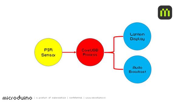
ContentsOverviewWhen you pass by, the Fortune Cat will wave to you with two eyes shining and meow. SchematicThe body will send pyroelectric infrared, sensor can detects it, when the sensor detects, will control lights change color, and the Audio module to play audio. Equipment
Preparation
and then start the Arduino IDE.
_303_FortuneCat.
"Done Uploading" appears, the program should have successfully been uploaded into the CoreUSB. Program description
#define humanHotSensor 4//PIR sensor pin number
#define PIN 6//color light pin number
#define SERVOPIN SDA//servo pin

Adafruit_NeoPixel strip = Adafruit_NeoPixel(1, PIN,

NEO_GRB + NEO_KHZ800);
if (humanHotState) {
    colorWipe(strip.Color(125, 125, 125));
    updateServo();

    if (!playing) {
      Serial.println("play sound.....");
     // audio_play();
     audio_choose(1);
      playing = true;
    }
  }
Hardware Buildup
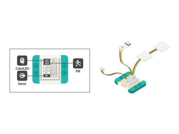
the sensors into the corresponding ports on the Hub module. To connect multiple LEDs in a series, follow the above diagram. Notice that the sensor cable connects to the IN ports of the LEDs. You can support up to six LEDs!
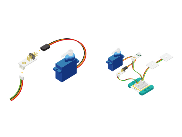
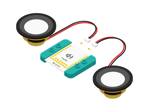
connect that to the IIC port in the Hub module.
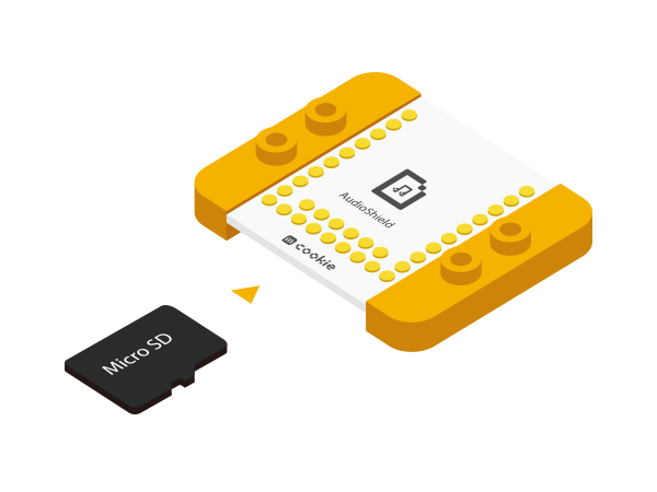
Then, copy a single greeting sound onto the micro SD card.
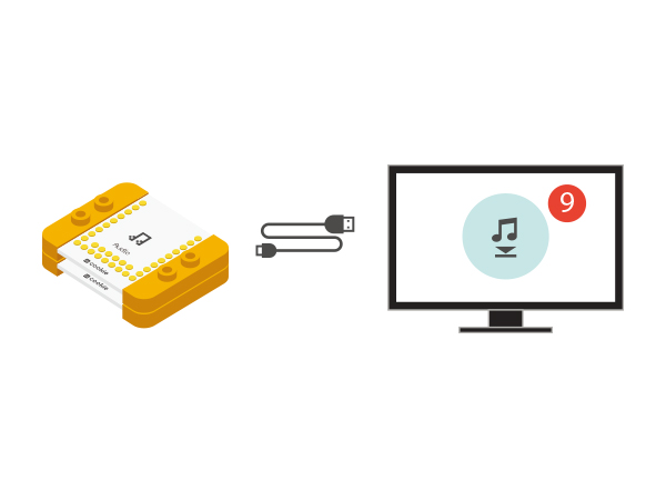
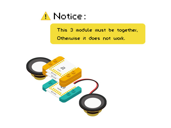
modules.
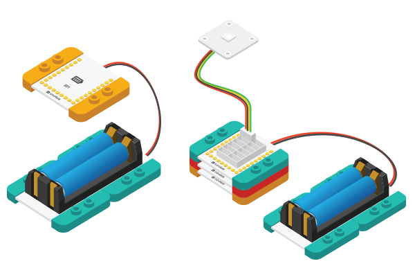
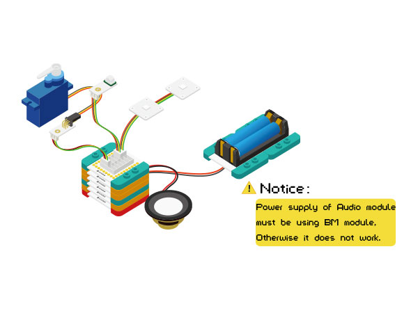
battery Management module.
(except Audio, AudioShield and Amplifier three together), Congratulation, the circuit part to build complete! ResultWhen you pass by, the Fortune Cat will wave to you with two eyes shining and meow. Video |
