Difference between revisions of "Open Source Self-balance Robot System"
From Microduino Wiki
(→Program Download) |
|||
| (16 intermediate revisions by 4 users not shown) | |||
| Line 20: | Line 20: | ||
|Module||Number||Function | |Module||Number||Function | ||
|- | |- | ||
| − | |[[Microduino-Core | + | |[[Microduino-Core]]||2||Core board |
|- | |- | ||
|[[Microduino-USBTTL]] ||1||Download program | |[[Microduino-USBTTL]] ||1||Download program | ||
|- | |- | ||
| − | |[[Microduino-nRF24]] || | + | |[[Microduino-nRF24]] ||2||Wireless communication |
|- | |- | ||
|[[Microduino-Motion]] ||1||Attitude detection | |[[Microduino-Motion]] ||1||Attitude detection | ||
| Line 37: | Line 37: | ||
|Module||Number||Function | |Module||Number||Function | ||
|- | |- | ||
| − | |[[Microduino-Core | + | |[[Microduino-Core]]||1||Core board |
|- | |- | ||
|[[Microduino-USBTTL]] ||1||Download program | |[[Microduino-USBTTL]] ||1||Download program | ||
| Line 85: | Line 85: | ||
==Program Download== | ==Program Download== | ||
| − | Download | + | Download source programs from the address below: |
| − | '''[https://github.com/Microduino/ | + | '''[https://github.com/Microduino/BalanceCar_Microduino_PID BalanceCar_Microduino]''' |
==Programming == | ==Programming == | ||
*Stack '''[[Microduino-Core+]]''' and '''[[Microduino-USBTTL]]''' together. | *Stack '''[[Microduino-Core+]]''' and '''[[Microduino-USBTTL]]''' together. | ||
| − | **Connect '''[[Microduino-USBTTL | + | **Connect '''[[Microduino-USBTTL]]''' with a USB cable for program uploading after that. |
| − | ** | + | **Attention: Please upload the program before stacking all modules. |
*Open Arduino IDE for Microduino environment. (For the buildup, please refer to: '''[[AVR Core:Getting started]]''') | *Open Arduino IDE for Microduino environment. (For the buildup, please refer to: '''[[AVR Core:Getting started]]''') | ||
*Click'''【Tool】''', select the right board card(Microduino-Core+) and the processor(Atmega644pa@16M,5V) and chose the corresponding port ''' COMX'''. | *Click'''【Tool】''', select the right board card(Microduino-Core+) and the processor(Atmega644pa@16M,5V) and chose the corresponding port ''' COMX'''. | ||
| − | *Click '''【File】'''->'''【Open】''', scan to the project program address, click ''' | + | *Click '''【File】'''->'''【Open】''', scan to the project program address, click '''"BalanceCar_Microduino.ino"''' and open it. |
| − | *After all that finished, please click '''"→"''' and download programs the development board. | + | *After all that finished, please click '''"→"''' and download programs the development board. |
==Buildup Steps== | ==Buildup Steps== | ||
| Line 134: | Line 134: | ||
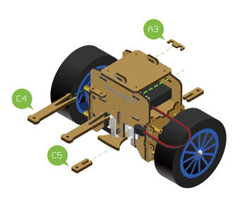
*Refer to the following Figure 5-2, use '''Structure-A3''', '''Structure-C4''' and '''Structure-C5''' to fixate the structure of the robot. | *Refer to the following Figure 5-2, use '''Structure-A3''', '''Structure-C4''' and '''Structure-C5''' to fixate the structure of the robot. | ||
[[File:Balancestep5-2.jpg||350px|center]] | [[File:Balancestep5-2.jpg||350px|center]] | ||
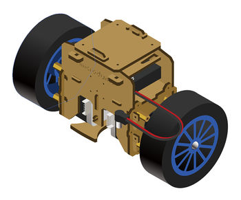
| − | * | + | *After Step5, it is as shown in the figure 5-3 : |
[[File:Balancestep5-3.jpg||350px|center]] | [[File:Balancestep5-3.jpg||350px|center]] | ||
| Line 164: | Line 164: | ||
*'''Joypad Communication Mode Configuration'''* | *'''Joypad Communication Mode Configuration'''* | ||
| − | *For the mode configuration, you can refer to: '''[https:// | + | *For the mode configuration, you can refer to: '''[https://wiki.microduino.cc/index.php/Microduino-Joypad_Getting_started#Communication_Protocol_Configuration Communication Mode Configuration]''' |
**When we use '''[[Microduino-nRF24]]''' as the '''Communication module''', for the Joypad, you can choose '''nRF mode'''. | **When we use '''[[Microduino-nRF24]]''' as the '''Communication module''', for the Joypad, you can choose '''nRF mode'''. | ||
*'''Joypad Battery Use'''* | *'''Joypad Battery Use'''* | ||
Latest revision as of 09:36, 4 August 2017
Contents[hide]Overview
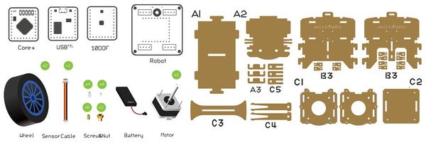
Bill of MaterialBill of Modules (Joypad Mode)
Bill of Modules (Bluetooth Mode)
Other Material
Program DownloadDownload source programs from the address below: BalanceCar_Microduino Programming
Buildup Steps
Operation Description
Joypad Remote Control Instructions
BLE Control Guide
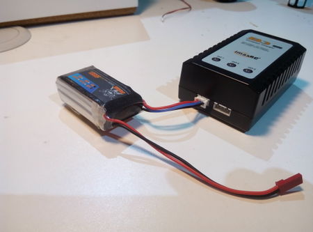
Lithium Battery Charging
Code Description
#define NRF_CHANNEL 70 //nRF channel
#define YAW    0
#define PITCH   1
#define ROLL    2
//Attitude sensor installation direction.
#define DIRECTION   PITCH
#define KP_CON 0.2 // 0.25
#define KI_CON 0
#define KD_CON 28  // 30 28 26
#define KP_THR 0.065  //0.08//0.065
#define KI_THR 0.0005//0.05
#define KD_THR 0
FAQ
Video |
