|
The product number of Sensor-Crash is: MSDS11
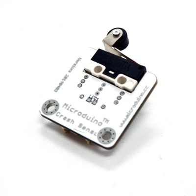
Sensor-Crash is a crash sensor, which is used to detect whether a crash has happened.
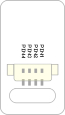
Introduction of Sensor Pin
Crash Sensor
| General Pin Out
|
Sensor / Trinket's Pin Out
|
| PIN1 (GND)
|
GND
|
| PIN2 (VCC)
|
VCC
|
| PIN3 (SIGNAL-A)
|
Digital Input
|
| PIN4 (SIGNAL-B)
|
Not Connected
|
- General Pin Out is the standard pin out of a Sensor / Trinket connector.
- Sensor / Trinket's Pin Out is this specific Sensor / Trinket's wiring in relation to the General Pin Out.
- SIGNAL-A / SIGNAL-B are signals that could be digital input, digital output, analog input or analog output. Or special signals such as serial communication (SoftwareSerial, IIC (I2C), etc) or other special signals.
- Not Connected refers to the Pin not being used for this particular Sensor / Trinket.
- Read more about the hub module.
About
Specification
- Size of the sensor
- Size of the board: 23.5mm*13mm
- 1.27mm-spacing 4Pin interface connected with sensorhub.
- CAD drawing of the sensor: File:Sensor CAD.zip
- Function description
- The static signal of the sensor is HIGH. After being pressed, the signal changes into LOW.
- Connection
- This sensor can be connected to the following interfaces of the core: D2~D13,A0~A7
Document
- Schematic diagram:
- Main sensors:
Usage
Basic Functionality
The Crash Sensor is a simple switch Single Pole Single Throw Switch (SPST). When the sensor is not press, the electrical path through it is "open" (electrons cannot flow through it). When the sensor is pressed, the electrical path through it is "closed" (electrons can flow through it).
Crash Sensor State Table
| State
|
Sensor Output
|
| Sensor is not pressed
|
HIGH
|
| Sensor is pressed
|
LOW
|
Program Download
Programming
Hardware Setup
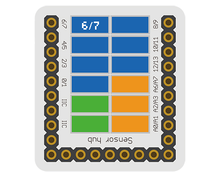
- Referring to the following diagram, connect the Sensor-Crash to digital port D6 of Microduino-Sensorhub.
Result
- After download, open the serial monitor.
- The static sensor signal is HIGH. After being pressed, it changes into LOW.
Application
Projects
History
Gallery
|


