Difference between revisions of "Sensor-Light-A1"

From Microduino Wiki
Jump to: navigation, search
(Basic Functionality)
Line 59: Line 59:
 
|-
 
|-
 
|10 Inches from the Sun
 
|10 Inches from the Sun
|- 1023
+
|1023
 
|}
 
|}
  

Revision as of 18:24, 18 August 2017

Language: English  • 中文
Microduino-Lightness

The product number of Sensor-Light-A1 is: MSDT42

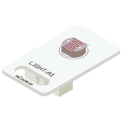
Sensor-Light-A1 is a photosensitive brightness detection sensor module.


The light sensor transforms the light signal into electric signal with the photosensitive resistance. Its sensitive wavelength is near that of the visible light, including the infrared and the ultraviolet.

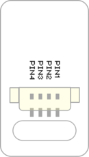
Description of the Sensor Pin

Sensor backpin.png

Light A1 Sensor
General Pin Out Sensor / Trinket's Pin Out
PIN1 (GND) GND
PIN2 (VCC) VCC
PIN3 (SIGNAL-A) Analog Input
PIN4 (SIGNAL-B) Not Connected
  • General Pin Out is the standard pin out of a Sensor / Trinket connector.
  • Sensor / Trinket's Pin Out is this specific Sensor / Trinket's wiring in relation to the General Pin Out.
  • SIGNAL-A / SIGNAL-B are signals that could be digital input, digital output, analog input or analog output. Or special signals such as serial communication (SoftwareSerial, IIC (I2C), etc) or other special signals.
  • Not Connected refers to the Pin not being used for this particular Sensor / Trinket.
  • Read more about the hub module.

Feature

  • Resistance photosensitive element, with high sensitivity.

Specification

  • Sensor voltage
    • 3.3V~5V working voltage
  • Size of the sensor
    • Size of the board: 23.5mm*13mm;
    • 1.27mm-spacing 4Pin interface connected with sensorhub;
    • CAD drawing of the sensor: File:Sensor CAD.zip
  • Function description
    • The sensor outputs the corresponding voltage according to the detected light intensity.
  • Connection
    • This sensor can be connected to the following interfaces of core: A0~A7

Document

  • Schematic diagram:
  • Main sensor:

Usage

Basic Functionality

The Light Sensor is an analog input sensor. It is able to detect light levels by using a photoresistor. A photoresistor is sensitive to the amount of light and changes its resistance based on light levels. When used in a voltage divider, different voltage levels will be produced based on the amount of light. A Core module can read the voltage value.

Light Sensor State Table
Light Amount Value Produce
No Light < 200
Finger Covering the Sensor 200~300
Ambient Light 700~900
10 Inches from the Sun 1023

Programming

Introduction

The Crash Sensor is used as a simple input pin. Therefore, the pinMode and digitalRead functions will be used.

Key Functions

  • Required Libraries: None
  • Key Functions:
    • pinMode(pin_number, pin_mode) - sets the mode for the pin
      • pin_number - is the pin number that the sensor is connected to
      • pin_mode - is the mode to set the pin to. Either INPUT or OUTPUT
    • digitalRead(pin_number) - Reads the value of the pin
      • pin_number - is the pin number that the sensor is connected to

Example

This is a simple example which outputs the state of the Crash Sensor to the serial port terminal.

Note: Important lines of code are highlighted.

//Define the pin the sensor is connected to
const int CRASH_SENSOR_PIN = 6;

void setup(){
  // put your setup code here, to run once:

  //Initial serial communication port at 9600 baud
  Serial.begin(9600);

  //Configure the pin into input mode
  pinMode(CRASH_SENSOR_PIN, INPUT);
}

void loop(){
  // put your main code here, to run repeatedly:

  //Perform a digital read and store the value into pin_state variable
  int pin_state = digitalRead(CRASH_SENSOR_PIN);

  //Check if the sensor's state is HIGH (not pressed)
  if(pin_state == HIGH){
    Serial.println("Crash sensor is not pressed!");
  }
  //Check if the sensor's state is LOW (pressed)
  else if(pin_state == LOW){
    Serial.println("Crash sensor is pressed!");
  }
  else{}

  //delay 100ms between loops
  delay(100);
}

Copy and paste the code above to the Arduino IDE or

Download the above example:

Program Download

Programming

  • Follow the Software Getting Started Guide.
  • Select the Board, Processor and Port.
  • Click [File]->[Open], browse to the project program address, and click "Microduino_Light_A1.ino" to open the program.
  • After confirming all these items are correct, click "→" to download the program to the development board.

Hardware Setup

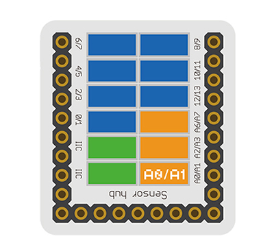
  • Referring to the following diagram, connect the Sensor-Light_A1 to the analog port A0/A1 of Microduino-Sensorhub.


Microduino-sLight A1.JPG


Result

  • After download, open the serial monitor.
  • The value displayed on serial monitor reflects the current light intensity detected by the sensor.

Application

It can feel the intensity of light around us. It can be used to detect the light intensity, and control the indoor lighting and object shading and so on.

Project

Purchase

History

Gallery

  • Front
File:Microduino-Light-F.JPG
Sensor-Light Front
  • Back
Retrieved from "https://wiki.microduinoinc.com/index.php?title=Sensor-Light-A1&oldid=21570"