Difference between revisions of "Sensor-Color LED"
(→Introduction of Sensor Pin) |
(→Development) |
||
| Line 52: | Line 52: | ||
*You can use the sample programs in the following IDE libraries to do experiment on your own: [https://github.com/wasdpkj/Microduino-IDE-Support/tree/master/arduino-ide-Support/%5B1.6.x%5D-hardware(library)/hardware/Microduino/avr/libraries '''_07_Sensor_LED_WS2812'''] | *You can use the sample programs in the following IDE libraries to do experiment on your own: [https://github.com/wasdpkj/Microduino-IDE-Support/tree/master/arduino-ide-Support/%5B1.6.x%5D-hardware(library)/hardware/Microduino/avr/libraries '''_07_Sensor_LED_WS2812'''] | ||
| − | == | + | ==Usage== |
| + | |||
| + | ===Basic Functionality=== | ||
| + | The ColorLED is a trinket which emits different colors based on the set red, green, and blue values. A Core module can control the ColorLED to output the desired colors. | ||
| + | |||
| + | Note: ColorLEDs can be connected together in a daisy chain fashion, and each ColorLED can be addressed individually using the index number. First ColorLED being 0, second ColorLED being 1, etc. | ||
| + | ===Programming=== | ||
| + | <tab name="Arduino for Microduino" style="width:100%;"> | ||
| + | ==Introduction== | ||
| + | The Buzzed Trinket is used as a output pin. Special functions on the Core module is used to generate a frequency signal to the Buzzer. | ||
| + | ==Key Functions== | ||
| + | *Required Libraries: None | ||
| + | *Key Functions: | ||
| + | ** '''tone(pin_number, frequency)''' - starts generating a frequency signal on the pin, will not stop until noTone(pin_number) is called '''([https://www.arduino.cc/en/Reference/Tone Read more])''' | ||
| + | ***'''pin_number''' - is the pin number that the trinket is connected to | ||
| + | ***'''frequency''' - a frequency value to generate on the pin | ||
| + | ** '''noTone(pin_number)''' - stops generating a frequency on the pin '''([https://www.arduino.cc/en/Reference/noTone Read more])''' | ||
| + | ***'''pin_number''' - is the pin number that the trinket is connected to | ||
| + | ** '''tone(pin_number, frequency, duration)''' - generates a frequency signal on the pin for a set amount of time '''([https://www.arduino.cc/en/Reference/Tone Read more])''' | ||
| + | ***'''pin_number''' - is the pin number that the trinket is connected to | ||
| + | ***'''frequency''' - a frequency value to generate on the pin | ||
| + | ***'''duration''' - the duration in milliseconds to generate the frequency signal | ||
| + | |||
| + | ==Example== | ||
| + | This is a simple example which: | ||
| + | *Starts the Buzzer at a 440hz frequency. | ||
| + | *Waits 1 second. | ||
| + | *Turns off the Buzzer. | ||
| + | *Wait 1 second. | ||
| + | *Runs the Buzzer at a 294hz frequency for 2 seconds | ||
| + | *Waits 5 seconds. | ||
| + | |||
| + | '''Note''': Important lines of code are highlighted. | ||
| + | |||
| + | <syntaxhighlight lang="cpp" highlight="1,2,14,15,18,19,24,25"> | ||
| + | //Define the pin the buzzer is connected to | ||
| + | const int BUZZER_PIN = 6; | ||
| + | |||
| + | void setup() { | ||
| + | // put your setup code here, to run once: | ||
| + | |||
| + | //Initial serial communication port at 9600 baud | ||
| + | Serial.begin(9600); | ||
| + | } | ||
| + | |||
| + | void loop() { | ||
| + | // put your main code here, to run repeatedly: | ||
| + | |||
| + | //Start the Buzzer with a 440hz frequency | ||
| + | tone(BUZZER_PIN, 440); | ||
| + | //Wait 1 second | ||
| + | delay(1000); | ||
| + | //Turn off the Buzzer | ||
| + | noTone(BUZZER_PIN); | ||
| + | |||
| + | //Wait 1 second | ||
| + | delay(1000); | ||
| + | |||
| + | //Run the Buzzer with a 294hz frequency for 2000 milliseconds (2 seconds) | ||
| + | tone(BUZZER_PIN, 294, 2000); | ||
| + | |||
| + | //Wait 5 seconds | ||
| + | delay(5000); | ||
| + | } | ||
| + | </syntaxhighlight> | ||
| + | Copy and paste the code above to the Arduino IDE or | ||
| + | |||
| + | Download the above example: n/a | ||
| + | </tab> | ||
| + | |||
===Program Download=== | ===Program Download=== | ||
*Download and unzip the program '''[[File:Sensor-Color-LED.zip]]''' | *Download and unzip the program '''[[File:Sensor-Color-LED.zip]]''' | ||
Revision as of 20:13, 18 August 2017
| Language: | English • 中文 |
|---|
|
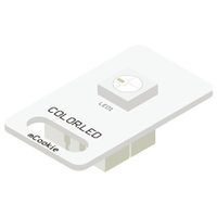
The product number of Sensor-Color LED is: MSDL11 Sensor-Color LED is full color LED, adopting single serial cascade protocol. Only one I/O port can control the RGB color of each LED on the line. If the power supply supports, it can support the cascade of as many as 1024 LEDs.
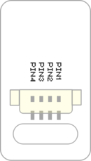
Contents[hide]Introduction of Sensor Pin
Features
Specification
Documents
UsageBasic FunctionalityThe ColorLED is a trinket which emits different colors based on the set red, green, and blue values. A Core module can control the ColorLED to output the desired colors. Note: ColorLEDs can be connected together in a daisy chain fashion, and each ColorLED can be addressed individually using the index number. First ColorLED being 0, second ColorLED being 1, etc. ProgrammingIntroductionThe Buzzed Trinket is used as a output pin. Special functions on the Core module is used to generate a frequency signal to the Buzzer. Key Functions
ExampleThis is a simple example which:
Note: Important lines of code are highlighted. //Define the pin the buzzer is connected to
const int BUZZER_PIN = 6;
void setup() {
// put your setup code here, to run once:
//Initial serial communication port at 9600 baud
Serial.begin(9600);
}
void loop() {
// put your main code here, to run repeatedly:
//Start the Buzzer with a 440hz frequency
tone(BUZZER_PIN, 440);
//Wait 1 second
delay(1000);
//Turn off the Buzzer
noTone(BUZZER_PIN);
//Wait 1 second
delay(1000);
//Run the Buzzer with a 294hz frequency for 2000 milliseconds (2 seconds)
tone(BUZZER_PIN, 294, 2000);
//Wait 5 seconds
delay(5000);
}Copy and paste the code above to the Arduino IDE or Download the above example: n/a Program Download
Programming
Hardware Setup
Results
Application
ProjectHistoryGallery
|


