Difference between revisions of "Sensor-Crash"
(→Introduction of Sensor Pin) |
(Revert back to early version for now until edits can be merged) |
||
| (44 intermediate revisions by 2 users not shown) | |||
| Line 1: | Line 1: | ||
{{Language|Sensor-Crash Sensor}} | {{Language|Sensor-Crash Sensor}} | ||
| − | {| style="width: | + | {| style="width: 80%;" |
|- | |- | ||
| | | | ||
| Line 7: | Line 7: | ||
The product number of Sensor-Crash is: '''MSDS11''' | The product number of Sensor-Crash is: '''MSDS11''' | ||
| − | Sensor-Crash is a crash sensor, which is used to detect whether a crash has happened | + | Sensor-Crash is a crash sensor, which is used to detect whether a crash has happened. |
| Line 13: | Line 13: | ||
==Introduction of Sensor Pin== | ==Introduction of Sensor Pin== | ||
| − | {{ | + | {{ST_Pinout |
| − | | | + | |st_name=Crash Sensor |
| − | | | + | |pin3=Digital Input |
| − | |||
}} | }} | ||
| − | + | =About= | |
| − | |||
| − | |||
| − | |||
| − | |||
| − | |||
| − | |||
| − | |||
| − | |||
| − | |||
| − | |||
| − | |||
| − | |||
| − | |||
| − | |||
| − | |||
| − | |||
| − | |||
| − | |||
| − | |||
| − | |||
| − | |||
| − | |||
| − | |||
| − | |||
| − | |||
| − | |||
| − | |||
| − | |||
| − | |||
| − | |||
| − | |||
| − | |||
| − | |||
| − | |||
| − | |||
==Specification== | ==Specification== | ||
| Line 72: | Line 36: | ||
==Document== | ==Document== | ||
| − | *Schematic diagram: ''' | + | *Schematic diagram: |
| − | * | + | *Main sensors: |
| + | |||
| + | ==Usage== | ||
| + | |||
| + | ===Basic Functionality=== | ||
| + | The Crash Sensor is a simple Single Pole Single Throw Switch (SPST). When the sensor is not press, the electrical path through it is "open" (electrons cannot flow through it). When the sensor is pressed, the electrical path through it is "closed" (electrons can flow through it). It is an input module which produces a HIGH or LOW voltage depending if pressed or not. A Core module can read the voltage value and determine the state of the Crash Sensor. | ||
| + | {| class="wikitable" | ||
| + | |+Crash Sensor State Table | ||
| + | |- | ||
| + | ! State | ||
| + | ! Voltage Level | ||
| + | |- | ||
| + | |Sensor is not pressed | ||
| + | |HIGH | ||
| + | |- | ||
| + | |Sensor is pressed | ||
| + | |LOW | ||
| + | |} | ||
| + | |||
| + | ===Programming=== | ||
| + | <tab name="Arduino for Microduino" style="width:100%;"> | ||
| + | ==Introduction== | ||
| + | The Crash Sensor is used as a simple input pin. Therefore, the '''pinMode''' and '''digitalRead''' functions will be used. | ||
| + | ==Key Functions== | ||
| + | *Required Libraries: None | ||
| + | *Key Functions: | ||
| + | ** '''pinMode(pin_number, pin_mode)''' - sets the mode for the pin | ||
| + | ***'''pin_number''' - is the pin number that the sensor is connected to | ||
| + | ***'''pin_mode''' - is the mode to set the pin to. Either '''INPUT''' or '''OUTPUT''' | ||
| + | ** '''digitalRead(pin_number)''' - Reads the value of the pin | ||
| + | ***'''pin_number''' - is the pin number that the sensor is connected to | ||
| + | |||
| + | ==Example== | ||
| + | This is a simple example which outputs the state of the Crash Sensor to the serial port terminal. | ||
| + | |||
| + | '''Note''': Important lines of code are highlighted. | ||
| + | |||
| + | <syntaxhighlight lang="cpp" highlight="1,2,10,11,17,18"> | ||
| + | //Define the pin the sensor is connected to | ||
| + | const int CRASH_SENSOR_PIN = 6; | ||
| + | |||
| + | void setup(){ | ||
| + | // put your setup code here, to run once: | ||
| + | |||
| + | //Initial serial communication port at 9600 baud | ||
| + | Serial.begin(9600); | ||
| + | |||
| + | //Configure the pin into input mode | ||
| + | pinMode(CRASH_SENSOR_PIN, INPUT); | ||
| + | } | ||
| + | |||
| + | void loop(){ | ||
| + | // put your main code here, to run repeatedly: | ||
| + | |||
| + | //Perform a digital read and store the value into pin_state variable | ||
| + | int pin_state = digitalRead(CRASH_SENSOR_PIN); | ||
| + | |||
| + | //Check if the sensor's state is HIGH (not pressed) | ||
| + | if(pin_state == HIGH){ | ||
| + | Serial.println("Crash sensor is not pressed!"); | ||
| + | } | ||
| + | //Check if the sensor's state is LOW (pressed) | ||
| + | else if(pin_state == LOW){ | ||
| + | Serial.println("Crash sensor is pressed!"); | ||
| + | } | ||
| + | else{} | ||
| + | |||
| + | //delay 100ms between loops | ||
| + | delay(100); | ||
| + | } | ||
| + | </syntaxhighlight> | ||
| + | Copy and paste the code above to the Arduino IDE or | ||
| + | |||
| + | Download the above example: n/a | ||
| + | |||
| + | *Open the Serial Monitor (magnifier glass on top right) and set 9600 baud. This will display the serial output. | ||
| + | </tab> | ||
| − | |||
===Program Download=== | ===Program Download=== | ||
*Download and unzip the program '''[[File:Sensor_Crash_Test.zip]]''' | *Download and unzip the program '''[[File:Sensor_Crash_Test.zip]]''' | ||
| + | *Or create a new sketch and copy & paste this code: '''https://gist.github.com/anonymous/d714e491f22fda1c42dd78f9e92b5eb4''' | ||
===Programming=== | ===Programming=== | ||
| Line 84: | Line 124: | ||
|nameB=[[Microduino-USBTTL]] | |nameB=[[Microduino-USBTTL]] | ||
|boardName=Microduino/mCookie-Core(328p), Atmega328P@16M,5V | |boardName=Microduino/mCookie-Core(328p), Atmega328P@16M,5V | ||
| − | |fileName= | + | |fileName=CrashTest.ino |
}} | }} | ||
Latest revision as of 20:30, 1 December 2017
| Language: | English • 中文 |
|---|
|
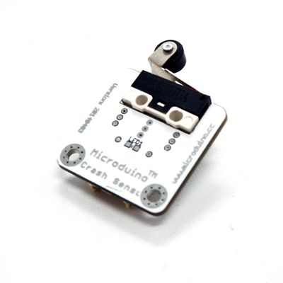
The product number of Sensor-Crash is: MSDS11 Sensor-Crash is a crash sensor, which is used to detect whether a crash has happened.
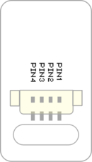
Contents[hide]Introduction of Sensor Pin
AboutSpecification
Document
UsageBasic FunctionalityThe Crash Sensor is a simple Single Pole Single Throw Switch (SPST). When the sensor is not press, the electrical path through it is "open" (electrons cannot flow through it). When the sensor is pressed, the electrical path through it is "closed" (electrons can flow through it). It is an input module which produces a HIGH or LOW voltage depending if pressed or not. A Core module can read the voltage value and determine the state of the Crash Sensor.
ProgrammingIntroductionThe Crash Sensor is used as a simple input pin. Therefore, the pinMode and digitalRead functions will be used. Key Functions
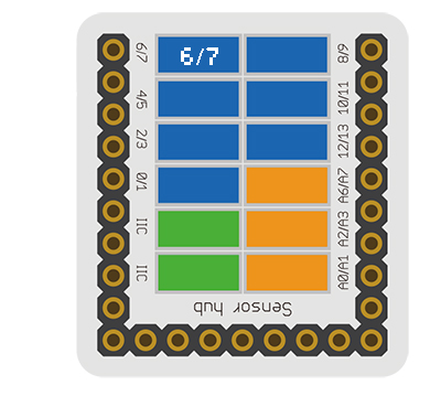
ExampleThis is a simple example which outputs the state of the Crash Sensor to the serial port terminal. Note: Important lines of code are highlighted. //Define the pin the sensor is connected to
const int CRASH_SENSOR_PIN = 6;
void setup(){
// put your setup code here, to run once:
//Initial serial communication port at 9600 baud
Serial.begin(9600);
//Configure the pin into input mode
pinMode(CRASH_SENSOR_PIN, INPUT);
}
void loop(){
// put your main code here, to run repeatedly:
//Perform a digital read and store the value into pin_state variable
int pin_state = digitalRead(CRASH_SENSOR_PIN);
//Check if the sensor's state is HIGH (not pressed)
if(pin_state == HIGH){
Serial.println("Crash sensor is not pressed!");
}
//Check if the sensor's state is LOW (pressed)
else if(pin_state == LOW){
Serial.println("Crash sensor is pressed!");
}
else{}
//delay 100ms between loops
delay(100);
}Copy and paste the code above to the Arduino IDE or Download the above example: n/a
Program Download
Programming
Hardware Setup
Result
Application
ProjectsHistoryGallery
|


