Difference between revisions of "Lesson 44--Microduino Matrix keyboard"
(Created page with "{{Language | 第四十四课--Microduino 矩阵键盘使用}} {| style="width: 800px;" |- | ==Objective== Understanding the principle of matrix keyboard and learn how to use M...") |
|||
| Line 50: | Line 50: | ||
==Video== | ==Video== | ||
| − | + | ||
|} | |} | ||
Latest revision as of 10:35, 27 July 2016
| Language: | English • 中文 |
|---|
ContentsObjectiveUnderstanding the principle of matrix keyboard and learn how to use Microduino read each key's value of matrix keyboard Equipment
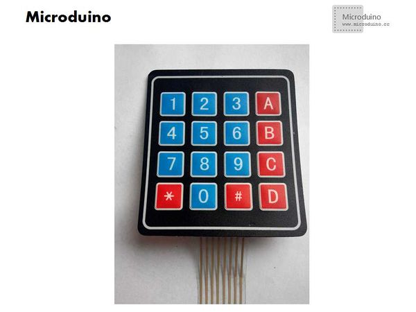
Matrix keyboardMatrix keyboard's structure is similar to the matrix of the keyboard group. When many keys in the keyboard, in order to reduce the occupation of the I/O port, we can use matrix keyboard. Such as the 4 * 4 matrix keyboard has 8 signal lines, then can control 16 buttons.
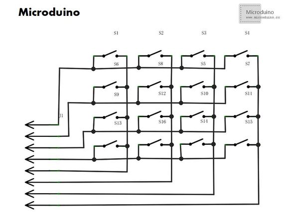
Each the horizontal and vertical line in the intersections are not directly connected, but through a button to connect them.
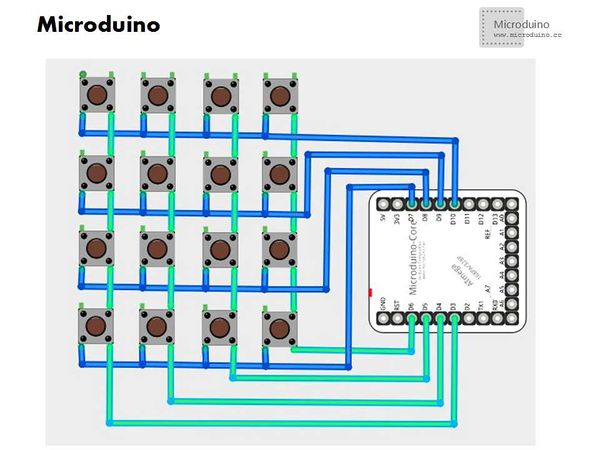
Column line through the resistance connects to power anode, and set the Microduino I/O ports connected to row line as output, the column line connected the I/O port as input. So when there is no button was pressed, all the input is high level, on behalf of no key pressed. Row line output is low level, once the key was pressed, the input line will be lower, so through reading the input line state can know if there is a key press. SchematicIf player don't have the matrix keyboard, you can use the independent keyboard to combine. Program
Debug
Method:From the schematic diagram, we can see that if the first button is pressed, corresponding to the first row line and column line that two wire connected. So we can use a multimeter ohm file to judge, use the pin to connect any two wires respectively, and then press the button, to see if in the conduction state, so that it can distinguish 8 lines how to connect the row and column.
Press the button and observe the OLED, check the value. Extension
ResultUse the Microduino to read the button on matrix keyboard and display the information on OLED. Playser also can make other application, such as combination lock Video |


