Difference between revisions of "Bluetooth Night Light"
| Line 31: | Line 31: | ||
==Preparation== | ==Preparation== | ||
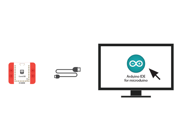
| − | *Setup | + | *Setup 1: Use a USB cable to connect the CoreUSB and PC/Mac, then open Arduino IDE. |
[[File:CoreUSB_Ble_pc.jpg|600px|center]] | [[File:CoreUSB_Ble_pc.jpg|600px|center]] | ||
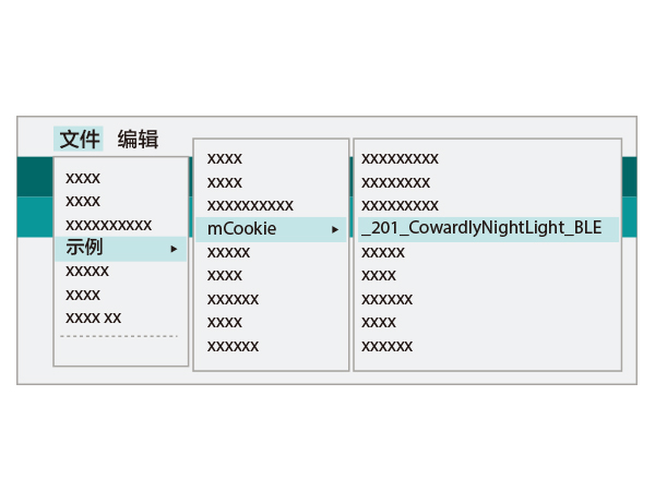
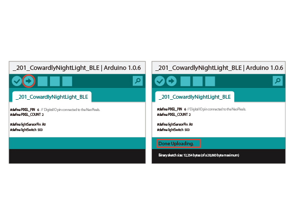
| − | *Setup | + | *Setup 2: Click file >examples > mCookie > _201_CowardlyNightLight_BLE, and download the program. |
[[File: light_indicator-ino.jpg|600px|center]] | [[File: light_indicator-ino.jpg|600px|center]] | ||
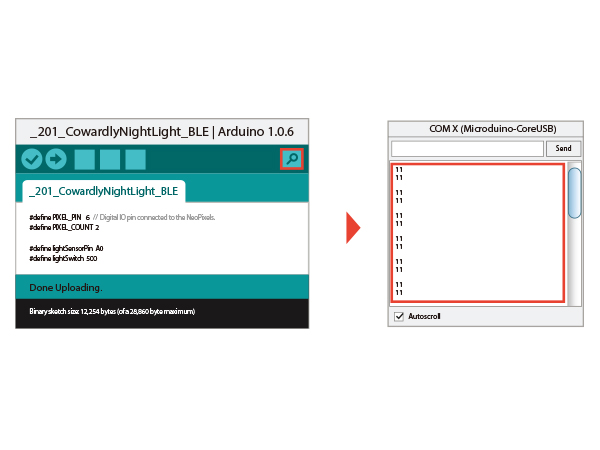
| − | * Setup | + | * Setup 3: Load the code, choose the right board and COM port for program download after compiling. |
[[File: light_indicator-com.jpg|600px|center]] | [[File: light_indicator-com.jpg|600px|center]] | ||
==Program Description== | ==Program Description== | ||
| − | + | "ble()" function is for Bluetooth data receiving and light control. | |
*Define Bluetooth Communication serial port. | *Define Bluetooth Communication serial port. | ||
<source lang="cpp"> | <source lang="cpp"> | ||
| Line 80: | Line 80: | ||
==Hardware Buildup == | ==Hardware Buildup == | ||
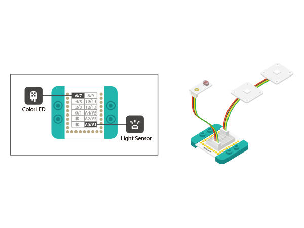
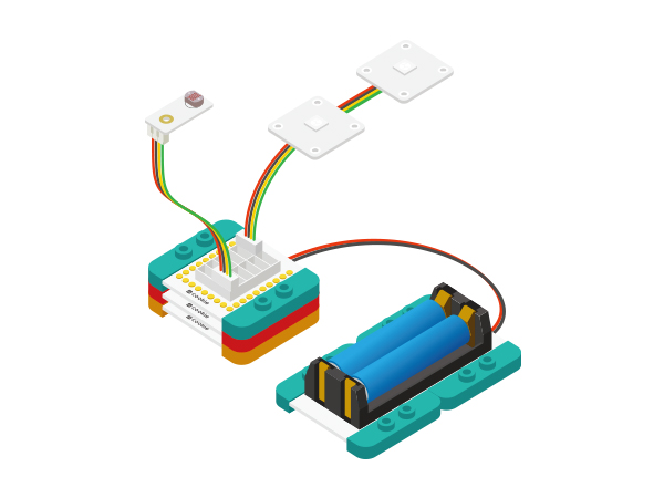
| − | *Setup | + | *Setup 1: Connect the Color LED to the Sensorhub D6 and the Light sensor to A0. |
[[File:night_colorled_ble.jpg|600px|center]] | [[File:night_colorled_ble.jpg|600px|center]] | ||
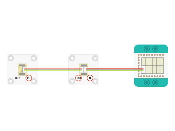
| − | For the connection of LED, please refer to the picture below. Please be noted of the connection order, which is from LED's IN | + | For the connection of LED, please refer to the picture below. Please be noted of the connection order, which is from LED's IN interface e to OUT. Here you can control two LED lights at most. |
[[File:CoreUSB_Ble_steup11.jpg|600px|center]] | [[File:CoreUSB_Ble_steup11.jpg|600px|center]] | ||
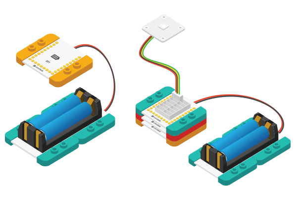
| − | *Setup | + | *Setup 2: Connect the activated battery box with the BM module. |
[[File:CoreUSB_Ble_steup2.jpg|600px|center]] | [[File:CoreUSB_Ble_steup2.jpg|600px|center]] | ||
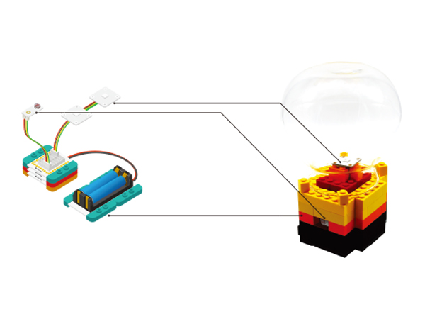
| − | *Setup | + | *Setup 3: Stack all modules together without a fixed order. Congratulations! You've finished the circuit buildup. |
[[File:CoreUSB_night led_steup3.jpg|600px|center]] | [[File:CoreUSB_night led_steup3.jpg|600px|center]] | ||
==APP Debugging== | ==APP Debugging== | ||
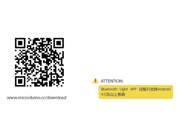
| − | *Setup | + | *Setup 1: Scan the two-dimensional code on the left, download Bluetooth Light APP. |
[[File:app_Ble_steup1.jpg|600px|center]] | [[File:app_Ble_steup1.jpg|600px|center]] | ||
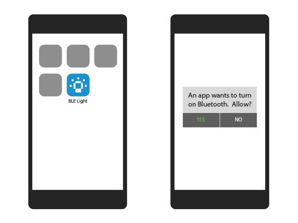
| − | *Setup | + | *Setup 2: Open the APP after the download and installation. The system will remind you to choose to open Bluetooth if it is disconnected. |
[[File:app_Ble_steup2.jpg|600px|center]] | [[File:app_Ble_steup2.jpg|600px|center]] | ||
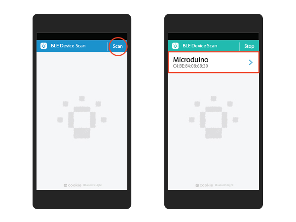
| − | *Setup | + | *Setup 3: Click Scan and the phone will start searching Bluetooth devices, which are displayed below. Here you can select Microduino device. |
[[File:app_Ble_steup3.jpg|600px|center]] | [[File:app_Ble_steup3.jpg|600px|center]] | ||
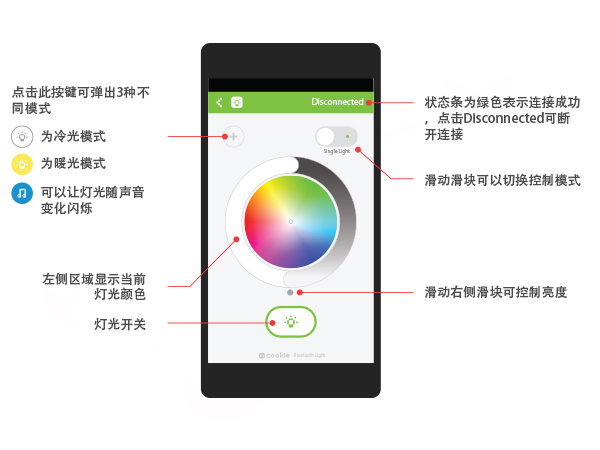
| − | *Setup | + | *Setup 4: After the connection, you can use your phone to control the light. |
[[File:app_Ble_steup4.jpg|600px|center]] | [[File:app_Ble_steup4.jpg|600px|center]] | ||
Latest revision as of 06:59, 30 September 2016
| Language: | English • 中文 |
|---|
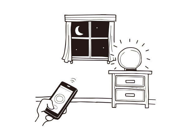
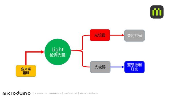
ContentsObjectiveWhen it gets dark, the night light starts to work. You can control the color and brightness of the light through Bluetooth. PrincipleWith the Light sensor to detect light intensity, so system can tell the light status. If the surrounding light is too strong, the Color LED light will turn off. You can use phone Bluetooth to control the color of the light. Equipment
Preparation
Program Description"ble()" function is for Bluetooth data receiving and light control.
#define my_Serial Serial1
#define PIXEL_PIN    6    // Digital IO pin connected to the NeoPixels.
#define PIXEL_COUNT  2

#define lightSensorPin  A0
#define lightSwitch 700
sensorValue = analogRead(lightSensorPin);
  if(sensorValue>lightSwitch) {
    Serial.println(sensorValue);
    strip.setPixelColor(0, strip.Color(0, 0, 0));
    strip.setPixelColor(1, strip.Color(0, 0, 0));
    strip.show();
  } else {
      ble();
      if (!color_en) {
        for (int i = 0; i < 1; i++)
          rainbow(10);
      }
  }
Code Debugging
The current setting value is 700. You can try to change the value in the program according to the previously detected data and download the program to see what happens. Hardware Buildup
For the connection of LED, please refer to the picture below. Please be noted of the connection order, which is from LED's IN interface e to OUT. Here you can control two LED lights at most.
APP Debugging
ResultCover the light sensor, or go into the dark environment, the LED light will shine. Then you can use the Bluetooth to control the color of the light. You can also build a beautiful look through Lego since mCookie can be freely stacked LEGO boards. Video |
