Difference between revisions of "Time-lapse Photography"

From Microduino Wiki
Jump to: navigation, search
 
(6 intermediate revisions by 2 users not shown)
(No difference)

Latest revision as of 23:37, 8 March 2017

Language: English  • 中文

Objective

Here we use the Microduino-IR Emitter to send infrared signal in the delayed time so as to control a SONY camera for picture taking and achieve time-lapse photography.

Experiment One: System sends signal in the delayed time

Equipment

Module Number Function
mCookie-CoreUSB 1 Core board
mCookie-Hub 1 Sensor pin board
Microduino-IR Emitter 1 Infrared emission sensor

Preparation

  • Setup 1: Connect the interface of the IR-Emitter to the D6 port of the Hub. (Note: The pin connection cannot be changed.)
  • Setup 2: Stack the CoreUSB, Hub and IR-Emitter together and them connect them to a computer with a USB cable.

Debugging

  • Open Arduino IDE and copy the following code into IDE.
#include <IRremote.h>

#define PHOTO 0xB4B8F

IRsend irsend;


void setup() {
  Serial.begin(115200);
  pinMode(6, OUTPUT);
}

void loop() {
  for (int i = 0; i < 3; i++)
  {
    irsend.sendSony(PHOTO, 20); // Sony code
    delay(12);
  }
  delay(5000);
}
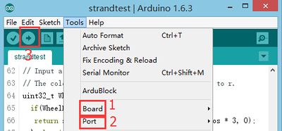
  • Select the right board and COM port, compile and download directly.
Upload.JPG
  • Turn on the camera and change to remote control mode.
  • Aim the IR Emitter to the camera and send signal every 5s. You can see the LED indicator on the IR Emitter flashes and hear the picture-taking sound at the same time.
  • It's wonderful to make the time-lapse pictures into GIF.

Program Debugging

  • Adopt " IRremote " infrared library to support the sending and receiving of the infrared signals.
  • "#define PHOTO 0xB4B8F" Define this SONY camera's infrared signal value.
  • Change the delay time; "delay(5000)" means five seconds.

Experiment Two: Key Control Picture-taking

Equipment

Module Number Function
mCookie-CoreUSB 1 Core board
mCookie-Hub 1 Sensor pinboard
Microduino-IR Emitter 1 Infrared emission sensor
Microduino-Crash 1 Crash sensor

Hardware Buildup

  • Setup 1: Connect the IR-Emitter to the Hub D6 and the Crash sensor to the Hub D8.
  • Setup 2: Stack the CoreUSB, Hub, Crash and IR-Emitter together and them connect them to a computer with a USB cable.

Software Debugging

  • Open Arduino IDE and copy the following code into IDE.
#include <IRremote.h>

#define PHOTO 0xB4B8F

IRsend irsend;

#define pushButton  8

int buttonState, num;

void setup() {
  Serial.begin(115200);
  pinMode(6, OUTPUT);
  pinMode(pushButton, INPUT);
}

void loop() {
  buttonState = digitalRead(pushButton);
  if (num != buttonState)
  {
    num = buttonState;
    if (num == 0)
    {
      take();
      Serial.println("take");
    }
  }
}

void take()
{
  for (int i = 0; i < 3; i++)
  {
    irsend.sendSony(PHOTO, 20); // Sony code
    delay(12);
  }
}
  • Result:

You can target the IR Emitter to the camera's infrared receiver, then set the camera to remote control mode, press the key and button and the camera takes picture once.

Program Description

  • When pressing, the status is changed from "1" to "0". Conversely, the status changes from "0" to "1" when releasing the button. You can tell the status from the data change.
buttonState = digitalRead(pushButton);
  if (num != buttonState)
  {
    num = buttonState;
    if (num == 0)
    {
      take();
      Serial.println("take");
    }
  }
  • "!=" means "Not equal to", which only performs when the pressed value changes.

Video