Difference between revisions of "Sensor-Pulse"
From Microduino Wiki
m (Fengfeng moved page Microduino-Pulse to Sensor-Pulse) |
(→Introduction of Pins) |
||
| (10 intermediate revisions by one other user not shown) | |||
| Line 3: | Line 3: | ||
|- | |- | ||
| | | | ||
| − | [[File: Microduino- | + | [[File: Microduino-Pulse.jpg|400px|thumb|right| Sensor-Pulse]] |
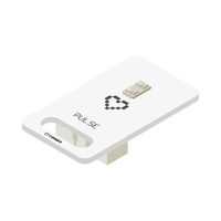
| − | + | The product number of Sensor-Pulse is: '''MSDI31''' | |
| − | |||
| − | |||
| − | |||
| − | |||
| − | |||
| + | Sensor-Pulse is a heart rate or pulse sensor of photoelectrical principle. | ||
| + | Sensor-Pulse takes advantage of the sensitivity of the infrared with specified wavelength to the change of the blood volume produced by the blood microcirculation in the end of the blood vessel to detect the change of fingertip blood caused by heart beat. | ||
| + | The sensor can output the completed pulse wave voltage signal reflecting the change of the fingertip blood volume. | ||
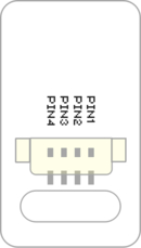
| + | ==Introduction of Pins== | ||
| + | {{ST_Pinout | ||
| + | |st_name=Pulse Sensor | ||
| + | |pin3=Analog Input | ||
| + | }} | ||
==Features== | ==Features== | ||
| − | * | + | *SON7015 sensor ultra-low consumption, and the power consumption is 0.2mA. |
| − | * | + | *With small size which is easy to install. |
| − | + | *Analog signal | |
==Specification== | ==Specification== | ||
| − | *Electrical specification | + | *Electrical specification |
| − | ** | + | **Input voltage: 3.3~5V, and 6V at most |
| − | ** | + | **Working current: 15uA |
| − | * | + | **Working temperature: -20~85℃ |
| − | * | + | **Output voltage: high level 5V, low level 0V |
| − | ** | ||
| − | |||
| − | |||
| − | |||
| − | |||
| − | |||
| − | |||
| − | |||
| − | |||
| − | |||
| − | * | + | *Size |
| − | ** | + | **Size of the board: 23.5mm*13mm |
| − | + | **1.27mm-spacing 4Pin interface connected with sensorhub | |
| − | + | **The CAD drawing of the sensor: '''[[File:Sensor_CAD.zip]]''' | |
| − | [[File: | ||
| − | + | *Function description | |
| + | **After press the sensor tightly on the skin, the digital output will be 1 or 0 along with the change of the blood. | ||
| + | |||
| + | *Connection | ||
| + | **This sensor can be connected to the following interfaces of core: '''D2~D13''' | ||
==Document== | ==Document== | ||
| − | * | + | *Schematic diagram: '''[[File: Sensor-Pulse.Zip]]''' |
| − | * | + | *Main chip: '''[[File:SON1303_datasheet.pdf ]]''' |
| + | *Extension document: [https://forum.microduino.cn/topic/259/microduino%E5%BF%83%E8%B7%B3%E6%A8%A1%E5%9D%97%E4%B8%AD%E6%96%AD%E6%B3%95%E6%B5%8B%E9%87%8F%E4%B8%A4%E5%88%99%E7%AE%80%E4%BB%8B Pulse Module Interrupt Method Measurement] | ||
| + | ==Development== | ||
| + | ===Program Download=== | ||
| + | *Download and unzip the program '''[[File:Sensor-Pulse_Test.zip]]''' | ||
| − | == | + | ===Programming=== |
| − | + | {{Upload | |
| − | + | |nameA=[[Microduino-Core]], [[Microduino-USBTTL]] | |
| − | + | |nameB=[[Microduino-USBTTL]] | |
| − | + | |boardName=Microduino/mCookie-Core(328p), Atmega328P@16M,5V | |
| − | + | |fileName=Sensor-Pulse Test.ino | |
| + | }} | ||
| − | === | + | ===Hardware Setup=== |
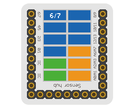
| + | *Referring to the following diagram, connect the Sensor-Pulse to the digital pin D6 of '''[[Microduino-Sensorhub]]'''. | ||
| + | <br> | ||
| + | [[file:Microduino-sensorhub_Crash.JPG|thumb|400px|left]] | ||
| + | <br style="clear: left"/> | ||
| − | * | + | ===Result=== |
| − | + | *After download, open the serial monitor. | |
| − | + | *The pulse sensor will detect the fingertip blood change caused by heart beat, and filter out some unstable elements through algorithm to get a more accurate value. | |
| − | * | ||
| − | |||
| − | |||
| − | |||
| − | |||
| − | |||
==Application== | ==Application== | ||
| − | + | *Real-Time Pulse Detection | |
| Line 83: | Line 82: | ||
==History== | ==History== | ||
| − | == | + | ==Gallery== |
| + | |||
| + | |||
| + | [[file: Microduino-Pulse-sensor-f.JPG|thumb|600px|center|Sensor-Pulse Front]] | ||
| − | + | [[file: Microduino-Pulse-sensor-b.JPG|thumb|600px|center|Sensor-Pulse Back]] | |
| − | [[file: Microduino- | ||
| − | |||
| − | |||
|} | |} | ||
Latest revision as of 23:32, 30 March 2017
| Language: | English • 中文 |
|---|
|
The product number of Sensor-Pulse is: MSDI31 Sensor-Pulse is a heart rate or pulse sensor of photoelectrical principle. Sensor-Pulse takes advantage of the sensitivity of the infrared with specified wavelength to the change of the blood volume produced by the blood microcirculation in the end of the blood vessel to detect the change of fingertip blood caused by heart beat. The sensor can output the completed pulse wave voltage signal reflecting the change of the fingertip blood volume.
ContentsIntroduction of Pins
Features
Specification
Document
DevelopmentProgram Download
Programming
Hardware Setup
Result
Application
ProjectPurchaseHistoryGalleryFile:Microduino-Pulse-sensor-f.JPG Sensor-Pulse Front File:Microduino-Pulse-sensor-b.JPG Sensor-Pulse Back |


