Difference between revisions of "Sensor-IR Receiver"

From Microduino Wiki
Jump to: navigation, search
(Introduction of Sensor Pins)
 
(One intermediate revision by one other user not shown)
Line 11: Line 11:
  
 
==Introduction of Sensor Pins==
 
==Introduction of Sensor Pins==
{{Sensor_explain
 
|nameA=[[Sensor-IR Receiver]]
 
|modeA=Digital signal input
 
|modeB=NC
 
}}


{{ST_Pinout
 
{{ST_Pinout
 
|st_name=IR Receiver
 
|st_name=IR Receiver
Line 60: Line 54:
  
 
===Hardware Setup===
 
===Hardware Setup===
*Refeering to the following diagram, connect the Sensor-IR Receiver to digital pin D6 of '''[[Microduino-Sensorhub/zh]]'''
+
*Referring to the following diagram, connect the Sensor-IR Receiver to digital pin D6 of '''[[Microduino-Sensorhub]]'''
 
<br>
 
<br>
 
[[file:Microduino-sensorhub_Crash.JPG|thumb|400px|left]]
 
[[file:Microduino-sensorhub_Crash.JPG|thumb|400px|left]]

Latest revision as of 06:53, 4 August 2017

Language: English  • 中文
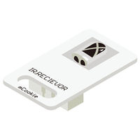
Microduino-IR-receiver

The product number of Sensor-IR-receiver is: MSDI22

Sensor-IR-receiver is an infrared receiving sensor.

Sensor-IR-Receiver contains a semiconductor device, which can turn the infrared light signal into electrical signal. Its core part is a PN junction with special material. Compared with the ordinary diode, it adopts great change in structure with a larger infrared receiving area, which makes the current increase accordingly.

Introduction of Sensor Pins

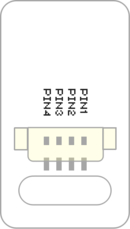
Sensor backpin.png

IR Receiver
General Pin Out Sensor / Trinket's Pin Out
PIN1 (GND) GND
PIN2 (VCC) VCC
PIN3 (SIGNAL-A) Digital Input
PIN4 (SIGNAL-B) Not Connected
  • General Pin Out is the standard pin out of a Sensor / Trinket connector.
  • Sensor / Trinket's Pin Out is this specific Sensor / Trinket's wiring in relation to the General Pin Out.
  • SIGNAL-A / SIGNAL-B are signals that could be digital input, digital output, analog input or analog output. Or special signals such as serial communication (SoftwareSerial, IIC (I2C), etc) or other special signals.
  • Not Connected refers to the Pin not being used for this particular Sensor / Trinket.
  • Read more about the hub module.

Features

  • Pulse type;
  • Long receiving distance and strong anti-interference ability;
  • With small size which is easy to install

Specification

  • Voltage
    • 3.3V~5V working voltage
  • Electronic specification
    • Working current: 15uA
    • Working temperature: -20~85℃
  • Size
    • Size of the board: 23.5mm*13mm
    • 1.27mm-spacing 4Pin interface connected with sensorhub
    • The CAD drawing of the sensor: File:Sensor CAD.zip
  • Technical parameters
    • The wave length is between 0.76~1.5μm
  • Connection
    • This sensor can be connected to the following interfaces of the core: D2~D13,A0~A7

Document

Development

Program Download

Programming

  • Follow the Software Getting Started Guide.
  • Select the Board, Processor and Port.
  • Click [File]->[Open], browse to the project program address, and click "Sensor-IR Receiver Test.ino" to open the program.
  • After confirming all these items are correct, click "→" to download the program to the development board.

Hardware Setup

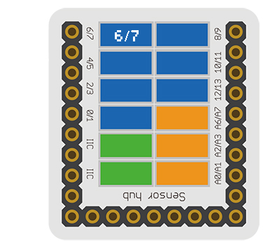
  • Referring to the following diagram, connect the Sensor-IR Receiver to digital pin D6 of Microduino-Sensorhub


Microduino-sensorhub Crash.JPG


Result

  • After download, open the serial monitor.
  • Send IR signal to the IR receiver with IR remote control, and you can see the LED on the IR Receiver flash once, representing that the IR Receiver has received the IR signal, and the decoded data will be printed out in the serial monitor at the same time.

Application

It can be used in infrared remote control, which is able to be matched with all kinds of infrared remote controller. You need to make sure the infrared signal type and protocol format before using.

History

Pictures

File:Microduino-IR-receiver-F1.JPG
Sensor-IR-receiver Front
File:Microduino-IR-receiver -b1.JPG
Sensor-IR-receiver Back
Retrieved from "https://wiki.microduinoinc.com/index.php?title=Sensor-IR_Receiver&oldid=21500"